
Delivery system for deployment of medical devices

a delivery system and medical device technology, applied in the field of medical device delivery system, can solve the problems of requiring prolonged patient hospitalization, large and often painful recovery, and aortic valve replacement necessitated surgery with its attendant risks and costs, and achieves the effect of minimal invasive delivery and little frictional engagemen

Active Publication Date: 2010-03-18
MEDTRONIC ARDIAN LUXEMBOURG SARL
View PDF104 Cites 239 Cited by
  • Summary
  • Abstract
  • Description
  • Claims
  • Application Information

AI Technical Summary

Benefits of technology

[0010]The invention provided comprises embodiments for minimally invasively delivering a medical device to a patient. The apparatus comprises a sheath that is connected at opposing ends to concentric tubes that move relative to each other in a manner that alternatively covers and exposes the medical device. A portion of the sheath is arranged so as to invert upon itself causing an inversion point. It is contemplated that axial movement of one tube relative to the other simultaneously moves the inversion point over or away from the medical device. In su...

Problems solved by technology

Historically, aortic valve replacement necessitated surgery with its attendant risks and costs.
This procedure has the disadvantage of requiring prolonged patient hospitalization, as well as extensive and often painful recovery.
Although safe and effective, surgical replacement presents advanced complexities and significant costs.
For some patients, however, surgery is not an option for one or many possible reasons.
As such, a large percentage of patients suffering from aortic disease go untreated.
In the case of transfemoral retrograde delivery, that would cause the outer tube to project well into the left ventricle, which is not desirable.
With minimally invasive cardiac valve replacement, as may be appreciated, loading of a self-expanding valved frame into a sheath (or capsule) can be difficult because of the frictional forces that inhibit movement of the frame into and out of the sheath.
Where precision is demanded, such friction requiring greater axial force to be applied makes accurate deployment more difficult.

Method used


Image

  • Delivery system for deployment of medical devices
  • Delivery system for deployment of medical devices
  • Delivery system for deployment of medical devices

Examples


Embodiment Construction

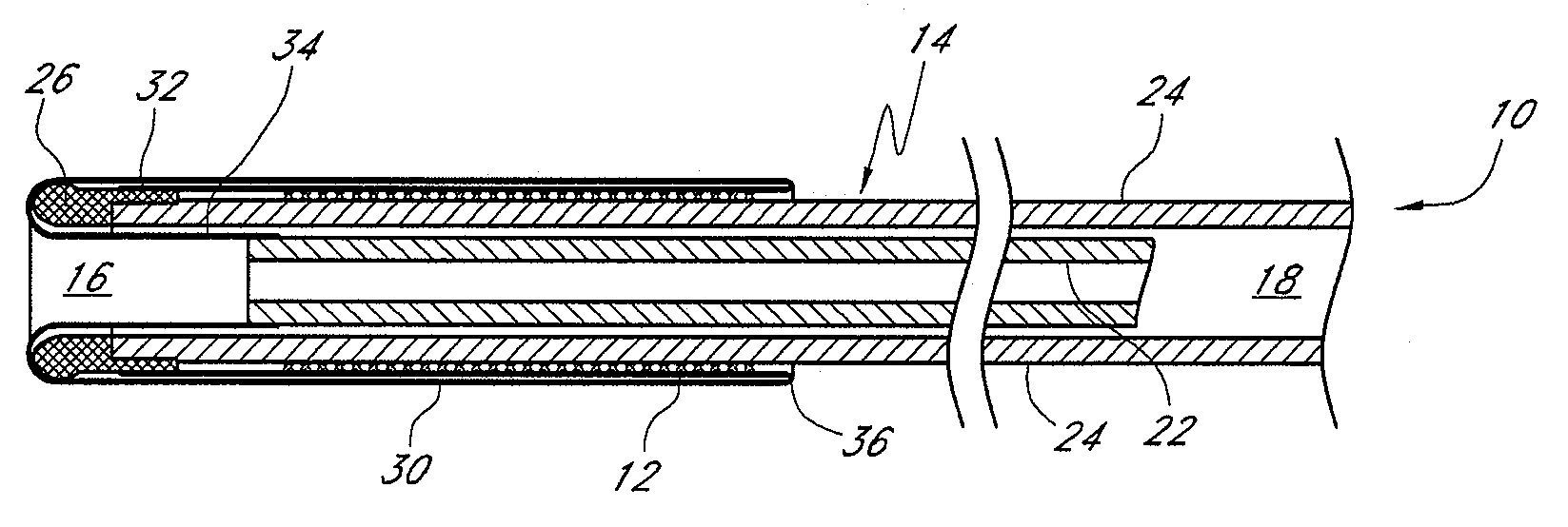
[0014]Referring to FIGS. 1A-C, one exemplary embodiment of an improved delivery system 10 for a medical device 12 comprises a catheter 14 having a distal end 16 and a proximal end 18. In the figures shown, and by way of example, the medical device 12 is a self-expanding frame.

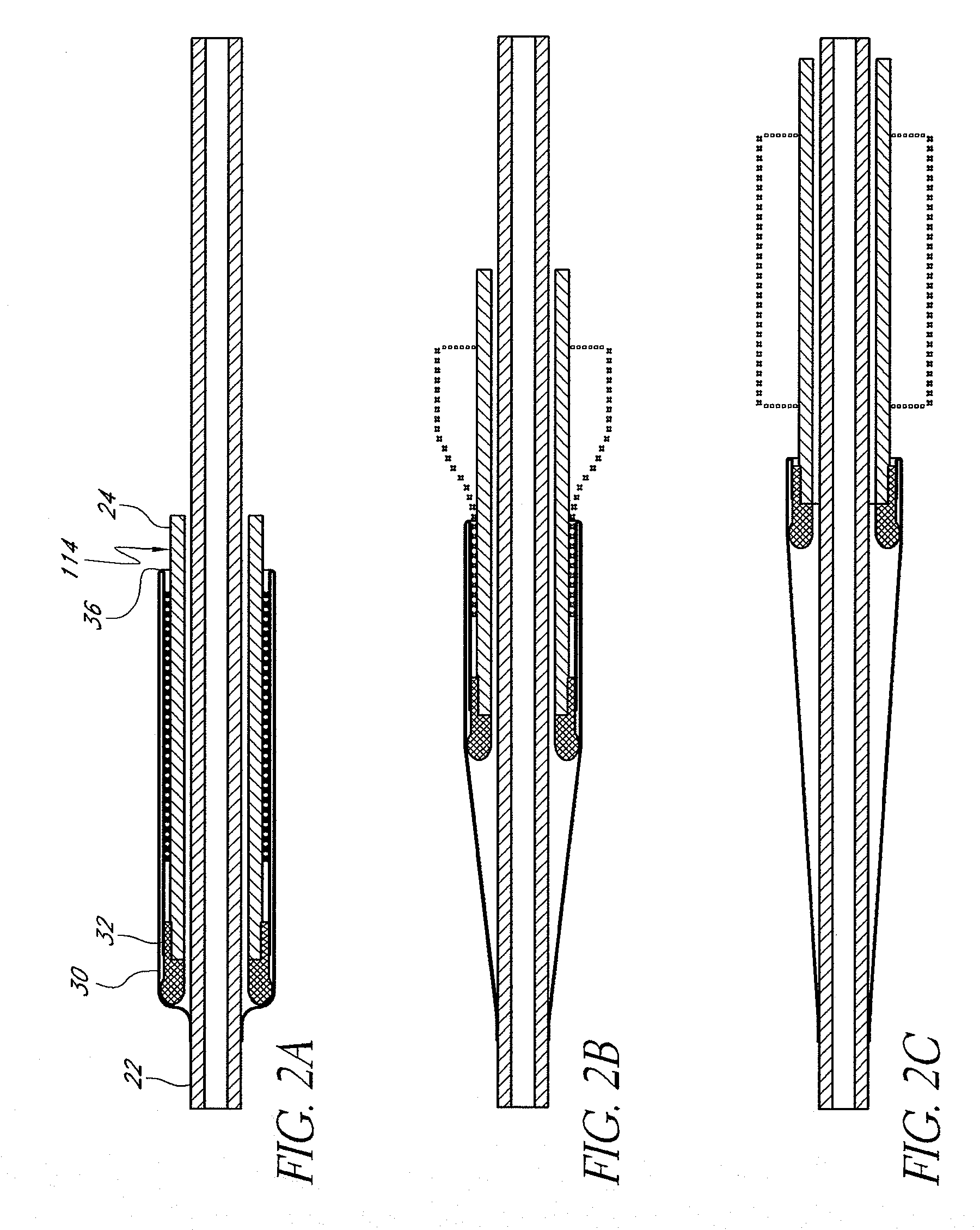
[0015]The catheter 14 further comprises a first inner tube 22 and an outer tube 24. At the distal end of the outer tube 24 is a cap 26 affixed to the outer tube 24. The cap 26 is preferably configured to have a smooth rounded surface at its distal most-end. By way of simplifying the description herein, FIG. 1A shows the system 10 such that the distal end of inner tube 22 is positioned proximal the distal end of outer tube 24, whereas FIG. 1B shows the inner tube 22 pulled in a proximal direction, with FIG. 1C showing it pulled further in the proximal direction.

[0016]The catheter 14 further comprises a sheath 30 preferably made of resilient pliable material, such as those used in the industry. The sheath may com...


PUM


Abstract

A catheter that comprises a sheath that is connected at opposing ends to concentric tubes that move relative to each other in a manner that alternatively covers and exposes a medical device loaded onto the catheter. A portion of the sheath is arranged so as to invert upon itself so that axial movement of one tube relative to the other simultaneously moves the inversion point over or away from the device, alternatively covering or exposing the device.

Description

BACKGROUND OF THE INVENTION[0001]1. Field of the Invention[0002]The present invention relates generally to an apparatus and method for loading a medical device onto a minimally invasive delivery system, such as a delivery catheter, and deploying the device in situ.[0003]2. Description of the Related Art[0004]Percutaneous aortic valve replacement (PAVR) technology is emerging that provides an extremely effective and safe alternative to therapies for aortic stenosis specifically, and aortic disease generally. Historically, aortic valve replacement necessitated surgery with its attendant risks and costs. The replacement of a deficient cardiac valve performed surgically requires first opening the thorax, placing the patient under extracorporeal circulation or peripheral aorto-venous heart assistance, temporarily stopping the heart, exposing and excising the deficient valve, and then implanting a prosthetic valve in its place. This procedure has the disadvantage of requiring prolonged pa...

Claims


Application Information

Patent Timeline
IPC IPC(8): A61M25/00A61M5/00A61M31/00
CPCA61F2/2436A61F2002/9665A61F2/95A61B17/34A61M5/158A61M2025/0687A61M2025/09091A61M2025/09175
Inventor KELLEY, GREGORY SCOTT
Owner MEDTRONIC ARDIAN LUXEMBOURG SARL
Features
  • Generate Ideas
  • Intellectual Property
  • Life Sciences
  • Materials
  • Tech Scout
  • Unparalleled Data Quality
  • Higher Quality Content
  • 60% Fewer Hallucinations
Learn More