Demand side management module

a technology of demand management and demand side, applied in the field of energy management, can solve the problems of no active control, no peak shaving method for an appliance such as a refrigerator will provide maximum benefit, etc., and achieve the effect of effective communication, low cost and significant savings

Active Publication Date: 2010-03-18
HAIER US APPLIANCE SOLUTIONS INC
View PDF99 Cites 127 Cited by
  • Summary
  • Abstract
  • Description
  • Claims
  • Application Information

AI Technical Summary

Benefits of technology

[0016]Use of RFID tags in one proposed system should offer significant savings since the RFID tags have become very low cost due to the proliferation of these devices in retail and will effectively allow the enabled appliance to effectively communicate with the utility meter (e.g., receive signals from the utility meter). This system makes it very easy for a customer to manage energy usage during peak demand periods and lowers the inconvenience level to the customer by not shutting off appliances in the home by the utility. When local storage and local generation are integrated into the system, then cost savings are seen by the customer. This system also solves the issue of rolling brownouts / blackouts caused by excessive power demand by lowering the overall demand. Also, the system allows the customer to pre-program choices into the system that will ultimately lower utility demand as well as save the customer money in the customer's utility billing. For instance, the customer may choose to disable the defrost cycle of a refrigerator during peak rate timeframes. This disclosure provides for the controller to “communicate” with the internal appliance control board and command the appliance to execute specific actions with no curtailment in the energy supply. This disclosure further provides a method of communicating data between a master device and one or more slave devices using RFID technology. This can be a number of states or signals, either using one or more passive RFID tags that resonate at different frequencies resonated by the master, or one or more active RFID tags that can store data that can be manipulated by the master device and read by the slave device(s). The states in either the passive or active RFID tags can then be read by the microcontroller on the slave device(s) and appropriate functions / actions can be taken based upon these signals.
[0017]Another exemplary embodiment uses continuous coded tones riding on carrier frequencies to transmit intelligence, for example, when one is merely passing rate information such as rate 1, 2, 3, or 4, using the tones to transmit the signals. One could further enhance the details of the messaging by assigning a binary number to a given tone, thus allowing one to “spell out” a message using binary coding with multiple tones. The appliance microcomputer would be programmed to respond to a given number that would arrive in binary format.
[0018]One advantage of this approach is that customers have complete control of their power. There have been proposals by utilities to shut off customers if they exceed demand limits or increase the number of rolling brownouts. This method also gives a customer finer granulity in their home in terms of control. A customer does not have to load shed a room just to manage a single device.
[0019]This disclosure also advantageously provides modes of load shedding in the appliance, lighting, or HVAC other than “on / off” to make the situation more acceptable from the perspective of the customer.

Problems solved by technology

Currently utilities charge a flat rate, but with increasing cost of fuel prices and high energy usage at certain parts of the day, utilities have to buy more energy to supply customers during peak demand.
However, there is no active control beyond the mere on / off switching.
One difficulty is that no peak shaving method for an appliance such as a refrigerator will provide a maximal benefit.
Similarly, known systems do not communicate directly with the appliance using a variety of communication methods and protocols, nor is a modular and standard method created for communication devices to interface and to communicate operational modes to the main controller of the appliance.

Method used


Image

  • Demand side management module
  • Demand side management module
  • Demand side management module

Examples


Embodiment Construction

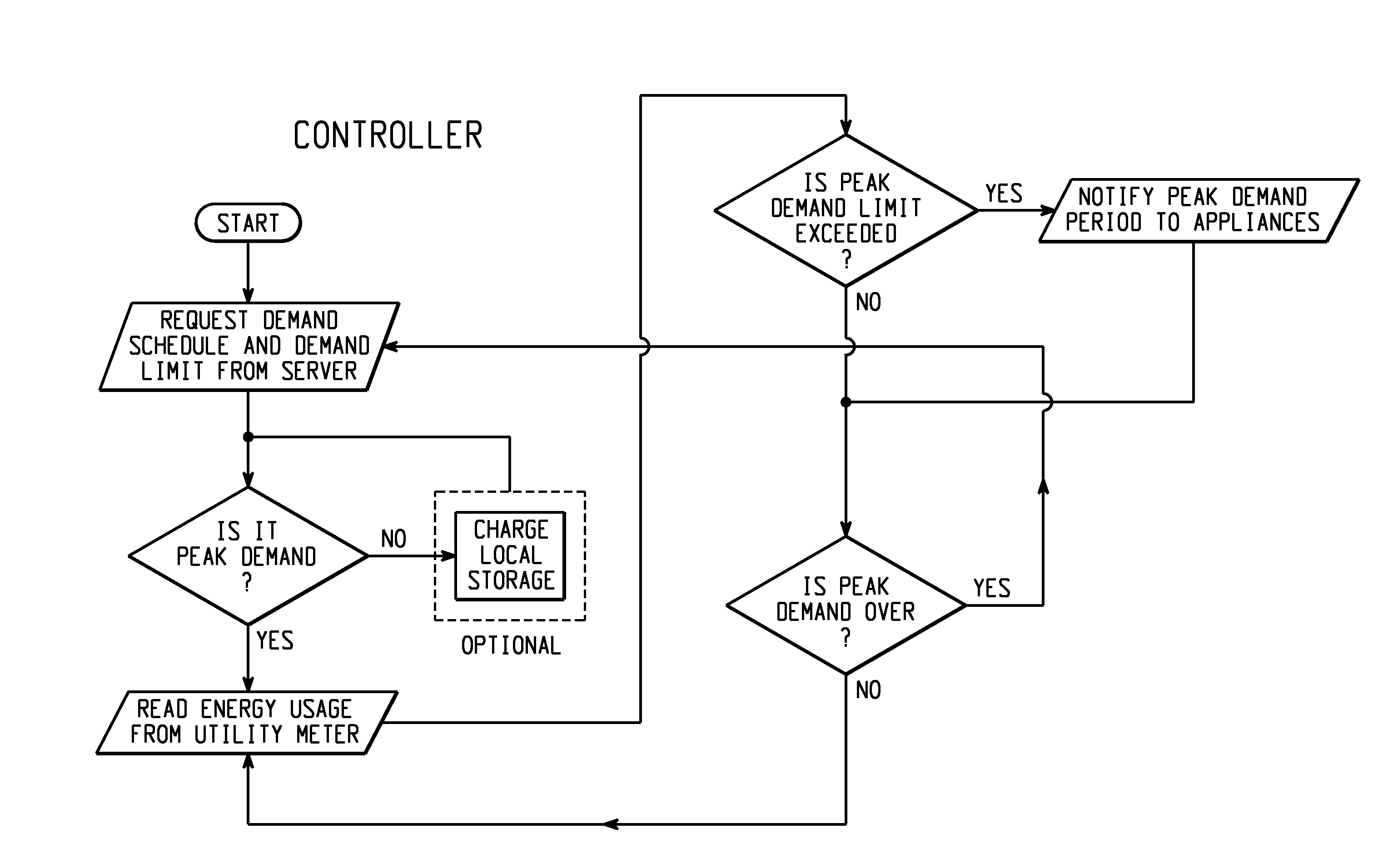
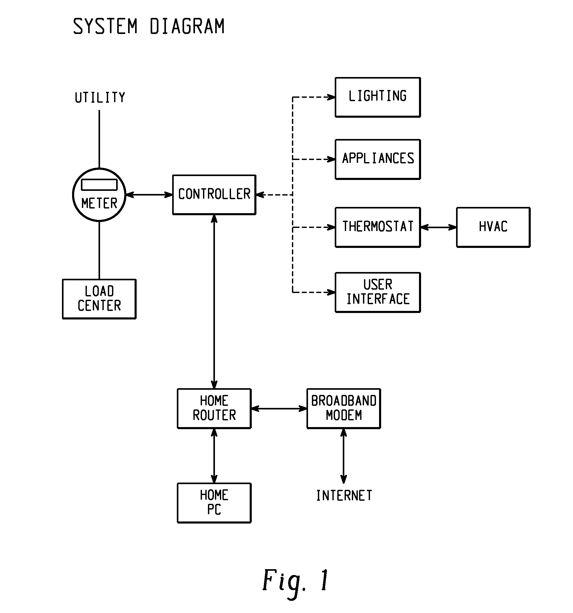
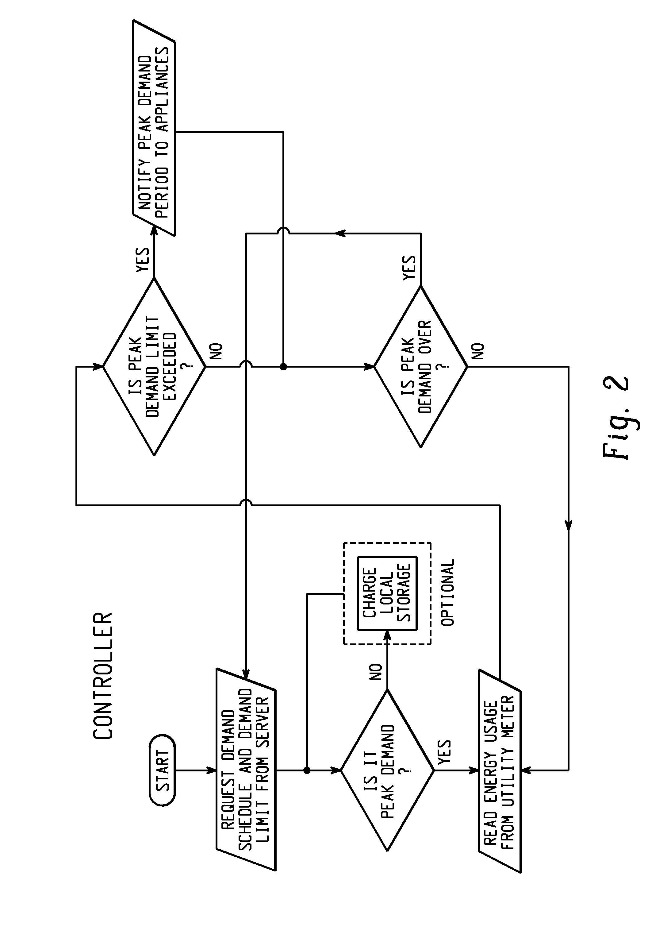
[0035]In one embodiment, a more advanced system is provided to handle energy management between the utility and the homeowner's appliances. The system can include one or more of the following: a controller, utility meter, communication network, intelligent appliances, local storage, local generator and / or demand server. Less advanced systems may actually allow the appliance to “communicate directly with the utility meter or mesh network through the DSSM (Demand Side Management Module) (FIG. 1). The demand server is a computer system that notifies the controller when the utility is in peak demand and what is the utility's current demand limit. A utility meter can also provide the controller the occurrence of peak demand and demand limit. The demand limit can also be set by the home owner. Additionally, the homeowner can choose to force various modes in the appliance control based on the rate the utility is charging at different times of the day. The controller will look at the energy...


PUM


Abstract

A household appliance system and method include an appliance control system having a common appliance interface provided on an appliance and a demand side management module connected to the common appliance interface. The module corresponds to one select utility of a plurality of utilities and is adapted to communicate with the one select utility of the plurality of utilities. The appliance control system operates the appliance based on communications with the one select utility through the module.

Description

[0001]The present application claims priority from U.S. Provisional Patent Application Ser. No. 61 / 097,082 filed 15 Sep. 2008, now Ser. No. ______, filed 15 Sep. 2009 (Attorney Docket No. 231,308 (GECZ 2 00948)); which provisional patent application is expressly incorporated herein by reference, in its entirety. In addition, cross-reference is made to commonly owned, copending applications Ser. No. ______, filed 15 Sep. 2009 (Attorney Docket No. 234503 (GECZ 00991)); Ser. No. ______, filed 15 Sep. 2009 (234622 (GECZ 2 00992)); Ser. No. ______, filed 15 Sep. 2009 (234930 (GECZ 2 00993)); Ser. No. ______, filed 15 Sep. 2009 (235012 (GECZ 2 00994)); Ser. No. ______, filed 15 Sep. 2009 (235215 (GECZ 2 00995)); Ser. No. ______, filed 15 Sep. 2009 (238022 (GECZ 2 00996)); Ser. No. ______, filed 15 Sep. 2009 (238338 (GECZ 2 00997)); Ser. No. ______, filed 15 Sep. 2009 (238404 (GECZ 2 00998)); Ser. No. ______, filed 15 Sep. 2009 (237845 (GECZ 2 00999)); Ser. No. ______, filed 15 Sep. 2009 (...

Claims


Application Information

Patent Timeline
Patent Type & Authority Applications(United States)
IPC IPC(8): G06F1/32G06F1/26
CPCG06Q50/06H02J3/14H02J13/0075H02J2003/146Y02B70/3225Y02B70/3275Y04S40/126Y04S20/224Y04S20/244G05B13/02Y02B70/3266Y04S20/242Y02B90/2653Y04S20/222H02J2310/64H02J2310/14H02J13/00017H02J13/00024H02J13/00026H02J13/00004Y04S40/124Y04S50/10H02J2310/66Y02B40/00F25D23/00F25D29/00G01R22/00G16Z99/00F25D21/04Y02B70/30Y02B90/20
Inventor WATSON, ERIC K.BESORE, JOHN K.BEYERLE, MICHAEL THOMASBINGHAM, DAVID C.FRANKS, DARINGUERNSEY, BYRONILICKOVIC, DARKOPATEL, MALLIKA RAVINDRASCHORK, BRIAN MICHAEL
Owner HAIER US APPLIANCE SOLUTIONS INC
Why Eureka
Try Eureka