Flywheel arrangement for an internal combustion engine

a technology of internal combustion engine and flywheel, which is applied in the direction of engine starters, machines/engines, muscle operated starters, etc., can solve the problems of high vibration levels, inability of engines to reach idle, and low natural frequency of such systems, so as to improve the overall vehicle driveability, improve the service life of various drive-train components, and reduce the level of torsional vibrations

Active Publication Date: 2010-03-25
VOLVO CAR CORP
View PDF17 Cites 14 Cited by
  • Summary
  • Abstract
  • Description
  • Claims
  • Application Information

AI Technical Summary

Benefits of technology

[0002]It is known to use dual-mass flywheels having a pair of rotating masses which rotate freely relative to one another to a limited extent and are interconnected by a compliant member such as a spring damper system to lower the level of torsional vibrations generated by a firing internal combustion engine. The mass of the flywheel is split into a first mass and a second mass where the first mass is attached to the engine side of the damper system and the second mass is attached to a clutch / transmission side of the damper system. Dual-mass flywheels of this kind can improve overall vehicle driveability and increase the service life of various drive-train components. Drive-train vibrations are reduced by such dual-mass flywheels, which reduces rattling and droning noises, particularly at low engine speeds. The resultant smoother low-speed running allows comfortable driving at lower speeds, which helps reduce fuel consumption. The transmission is also easier to shift because of the low mass to be synchronized, and there is less synchronization wear.
[0004]The present disclosure describes a flywheel arrangement for an internal combustion engine producing a reduced level of torsional vibration during engine start-up, where the arrangement comprises a starter motor having a pinion gear at an output shaft, which pinion gear is arranged in constant engagement with a corresponding crank gear of a crank wheel located between an engine block and a flywheel assembly of the engine, which crank wheel is operatively connected to a crankshaft of the engine via a one-way clutch unit.

Problems solved by technology

A major problem with prior art dual-mass flywheels is that the natural frequencies of such systems are relatively low.
This creates a problem when an engine is to be started in that the frequency of the torsional vibration excitation generated by the engine at some point in the engine start-up sequence, often below 400 rpm, matches the natural frequency of the dual-mass system causing high vibration levels and inhibiting the engine from reaching idle.
When passing through a resonance frequency in the starting sequence of the engine there is the possibility that the two flywheels move in opposite directions and only stop finally when reaching end positions e.g. as the springs of a torsional vibration damper become “solid”, potentially causing degradation of the flywheel assembly.

Method used


Image

  • Flywheel arrangement for an internal combustion engine
  • Flywheel arrangement for an internal combustion engine

Examples


Embodiment Construction

[0008]This disclosure is based on the realisation that it would be advantageous if the torsional natural frequency of a dual-mass flywheel system could be raised during engine start-up cranking and then lowered after engine start-up for more effective control of torsional vibration levels due to the engine firing in normal operation.

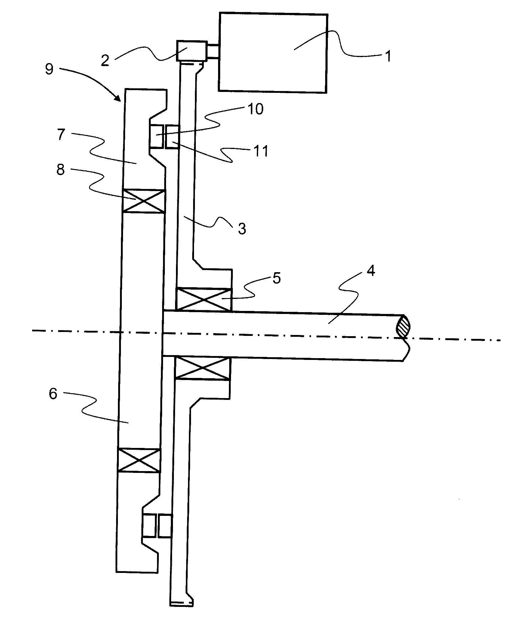
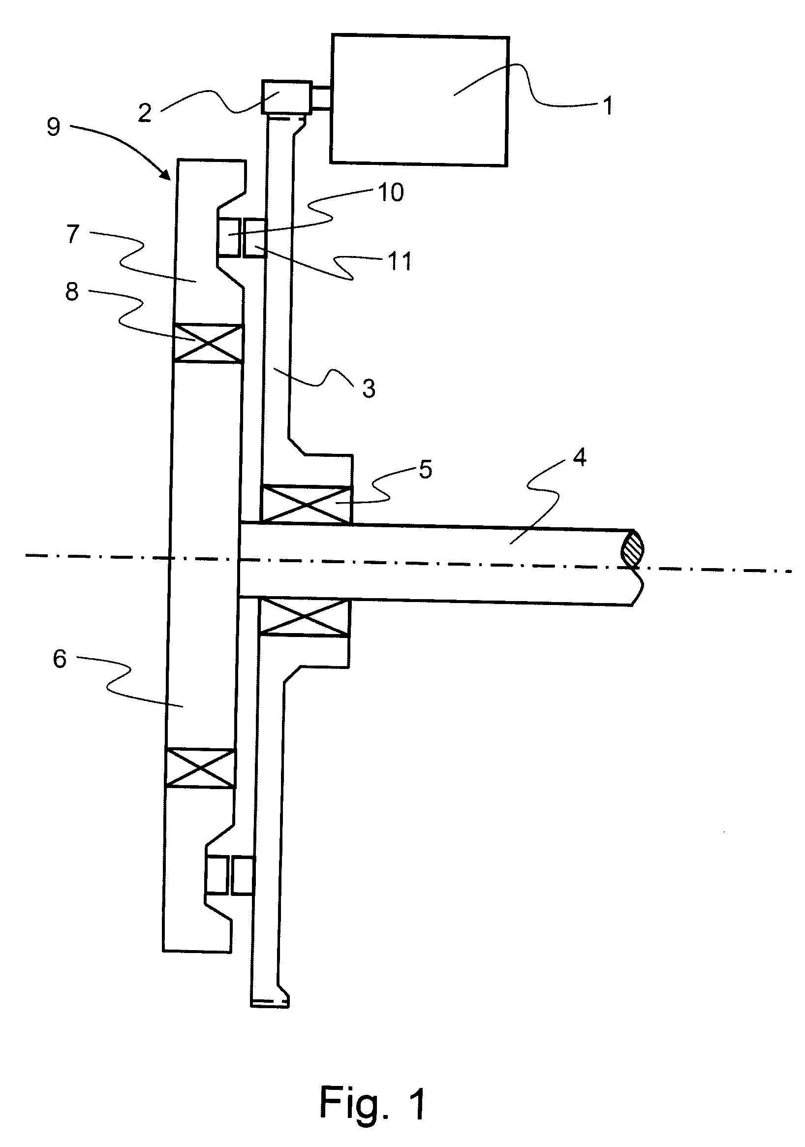
[0009]In a preferred first embodiment, as shown schematically in FIG. 1, a starter arrangement comprises a starter motor 1, e.g. an electrical starter motor, having a pinion gear 2 at an output shaft. The pinion gear 2 is arranged in constant engagement, e.g. through always meshing, with a corresponding crank gear of a crank wheel 3. The crank wheel 3 is located between an engine block (not shown) and a flywheel assembly 9 of the engine.

[0010]The crank wheel 3 is operatively connected to a crankshaft 4 of the engine via a one-way clutch unit 5, and is suitably a ring gear that is arranged to rotate with the starter motor 1 and freewheel when the engine r...


PUM


Abstract

An engine is disclosed having a flywheel arrangement comprising a starter motor (1) having a pinion gear (2) at an output shaft. The pinion gear (2) constantly engages a corresponding crank gear of a crank wheel (3) located between an engine block and a flywheel assembly (9) of the engine. The crank wheel (3) is operatively connected to a crankshaft (4) of the engine via a one-way clutch unit (5). The flywheel assembly (9) comprises a first flywheel body (6) connected to the crankshaft (4) of the engine. A second flywheel body (7) is rotatable relative to the first flywheel body (6) and coupled thereto such that is able to move elastically through a limited angular distance relative to the first flywheel body (6). An interlocking device includes at least one locking arrangement (8) and is adapted to produce an interlocking connection between the second flywheel body (7) and the first flywheel body (6) during cranking of the internal combustion engine.

Description

TECHNICAL FIELD[0001]The present disclosure is related to a flywheel arrangement for an internal combustion engine directed to reducing the level of torsional vibrations produced in the flywheel arrangement engine start-up.BACKGROUND AND SUMMARY[0002]It is known to use dual-mass flywheels having a pair of rotating masses which rotate freely relative to one another to a limited extent and are interconnected by a compliant member such as a spring damper system to lower the level of torsional vibrations generated by a firing internal combustion engine. The mass of the flywheel is split into a first mass and a second mass where the first mass is attached to the engine side of the damper system and the second mass is attached to a clutch / transmission side of the damper system. Dual-mass flywheels of this kind can improve overall vehicle driveability and increase the service life of various drive-train components. Drive-train vibrations are reduced by such dual-mass flywheels, which reduc...

Claims


Application Information

Patent Timeline
Patent Type & Authority Applications(United States)
IPC IPC(8): F02N1/00
CPCF02N11/00F16F15/31F16F15/1338F02N15/022
Inventor ALMHAGEN, PETTERGAST, PETER ULRIKFORSSELL, JONASSTENVALL, LARS JOHAN
Owner VOLVO CAR CORP
Why Eureka
Try Eureka