
External middle ear insufflation device

Inactive Publication Date: 2010-03-25
WOHL DANIEL L
View PDF8 Cites 21 Cited by
  • Summary
  • Abstract
  • Description
  • Claims
  • Application Information

AI Technical Summary

Benefits of technology

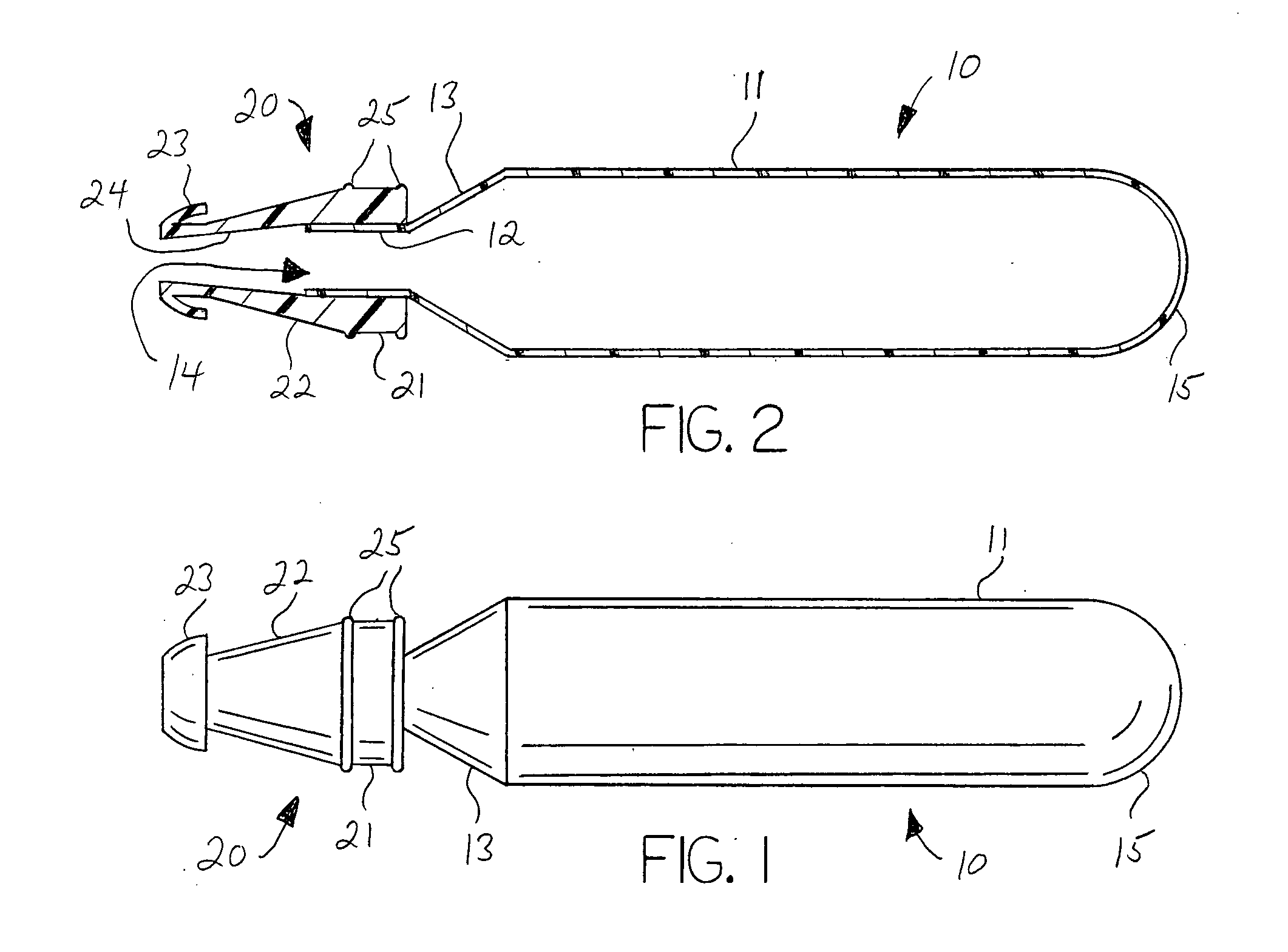
[0007]When air pressure differentials are encountered, the ear canal sealing member of the device is inserted into the ear canal so as to effectively block passage of air between the ear canal and the environment. When the external air pressure is greater than the air pressure in the middle ear, the bladder member is first squeezed to expel air within its interior, the ear canal sealing member is then inserted into the ear canal, and the bladder member is allowed to expand to pull air from the ear canal into the bladder member, thereby decreasing pressure within the ear canal, which is translated to the middle ear as the tympanic membrane responds by moving in a normal piston-like manner resulting in corresponding changes in the middle ear pressure. When the external air pressure is less than the air pressure in the middle ear, the bladder member is inserted in its expanded state and then squeezed using the fingers and thumb in order to increase pressure in the ear canal against tympanic membrane. In certain circumstances, repetitive pumping of the device by squeezing and releasing the bladder member may be needed to equalize the atmospheric air pressure differential by promoting air entry into the middle ear through the Eustachian Tube as the tympanic membrane moves back and forth, thereby relieving the pain and discomfort from pressure imbalance.

Problems solved by technology

In other cases, however, the Eustachian Tubes may not open sufficiently or may be blocked, as for example when a person is suffering from a cold or with young children whose Eustachian Tubes have not fully matured, with the pressure differential across the tympanic membrane resulting in discomfort or pain.
These techniques do not always work, and in the case of infants and young children, the child may not understand the parent's instructions.
The original method required a high pressure burst administered simultaneously with swallowing, which proved difficult to properly time.
In addition, the early systems lacked safeguards against the administration of excessive pressure.
The devices were often designed only to increase pressure within the Eustachian tube internal to the middle ear, and thus were not useful in circumstances where the external pressure is less than the internal pressure.
Even with improved devices, alleviating the discomfort and pain in young children and infants was hindered by the natural aversion to having air forced into the nasal cavity.

Method used


Image

  • External middle ear insufflation device
  • External middle ear insufflation device

Examples


Embodiment Construction

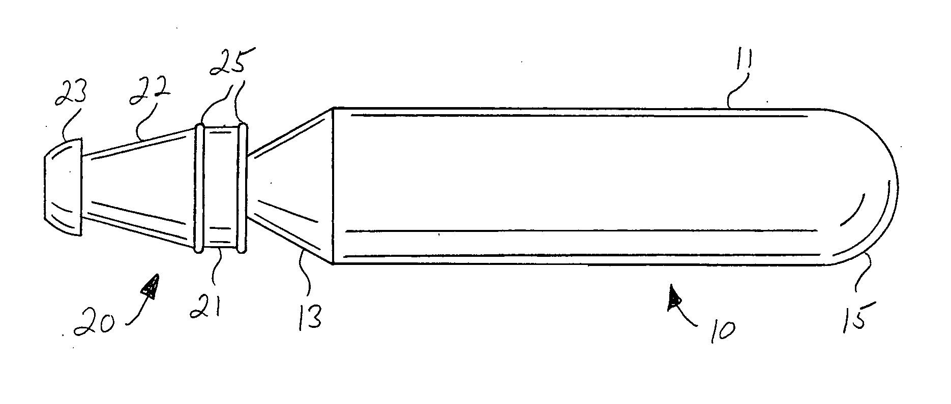
[0010]With reference to the drawings, the invention will now be described in detail with regard for the best mode and the preferred embodiment. In general, the invention is an external middle ear insufflation device and its method of use that rapidly equalizes pressure differentials between the external ear canal and the middle ear, such as would be encountered for example during the take off and landing phases of air travel, or with certain medical conditions. The device allows an individual to address pain and discomfort in his or her own ears, as well as addressing pain and discomfort in the ears of an infant or young child incapable of operating the device. The device transfers a relatively small, controlled amount of air within the ear canal during suction or expulsion operations.

[0011]As shown in the figures illustrating a representative embodiment of the invention, the middle ear insufflation device comprises a compressible bladder member 10 and an ear canal sealing member 20...


PUM


Abstract

A middle ear insufflation device to relieve pressure differential across the tympanic membrane resulting from rapid changes in altitude or intrinsic Eustachian Tube Dysfunction, the device having a compressible bladder member and an ear canal sealing member such that the bladder member can be compressed and released to reduce or increase pressure within the ear canal that is then translated across the tympanic membrane affecting internal pressure within the middle ear space, thereby helping to facilitate normalization of middle ear pressure through the Eustachian Tube.

Description

[0001]This application claims the benefit of U.S. Provisional Patent Application Ser. No. 61 / 192,756, filed Sep. 22, 2008.BACKGROUND OF THE INVENTION[0002]This invention relates generally to the field of devices and methods used to equalize air pressure differentials between the middle ear and the external ear canal resulting from rapid changes in altitude, such as occur during take off and landing of an airplane, or with primary Eustachian Tube Dysfunction as is commonly encountered in children.[0003]As an airplane rises to cruising altitude the air pressure within the ear canal, the region exterior to the tympanic membrane, drops rapidly, while the air pressure within the middle ear remains higher unless equalization occurs. During landing the opposite situation occurs, with the external air pressure now being greater than the internal air pressure. In most cases, sufficient air passes from inside the upper throat through the Eustachian Tubes into the middle ear to equalize the ai...

Claims


Application Information

Patent Timeline
IPC IPC(8): A61F11/08
CPCA61F11/002A61F11/00A61F11/202
Inventor WOHL, DANIEL L.
Owner WOHL DANIEL L
Learn More