Heat exchanging element

a technology of heat exchanger and element, which is applied in the direction of laminated elements, heating types, lighting and heating apparatus, etc., can solve the problems of reducing the effective area of the heat exchanger plate, difficult to make them uniform, and reducing the heat exchange efficiency, so as to achieve the effect of reducing air passage drift, high heat exchange efficiency, and maintaining structural strength

Inactive Publication Date: 2010-03-25
PANASONIC CORP
View PDF3 Cites 24 Cited by
  • Summary
  • Abstract
  • Description
  • Claims
  • Application Information

AI Technical Summary

Benefits of technology

[0011]In view of the conventional problems, it is an object of the present invention to provide a heat exchanging element that eliminates drift in air passages while maintaining its structural strength, thereby providing high heat exchange efficiency and that also prevents airflow leakage due to peeling between the heat exchanger plates and other components.
[0012]The heat exchanging element according to the present invention performs heat exchange by circulating a primary airflow and a secondary airflow through their corresponding air passages alternately formed between a plurality of heat exchanger plates laminated on each other with a predetermined spacing. The heat exchanging element includes counterflow regions in which the primary airflow and the secondary airflow flow opposite to each other with the heat exchanger plates therebetween. The heat exchanging element further includes shiel

Problems solved by technology

This causes primary and secondary airflows “M” and “N” circulating through heat exchanger 101 to drift, thereby decreasing the heat exchange efficiency.
These junctions cause a decrease in the effective area of the heat exchanger plates.
However, in the actual production process, it is difficult to make them uniform because fins

Method used


Image

  • Heat exchanging element
  • Heat exchanging element
  • Heat exchanging element

Examples


first embodiment

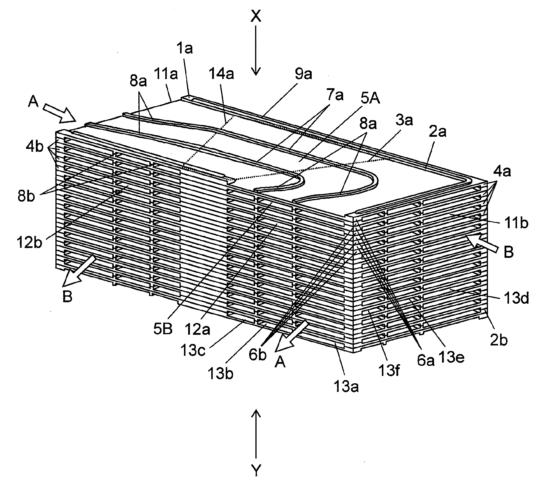
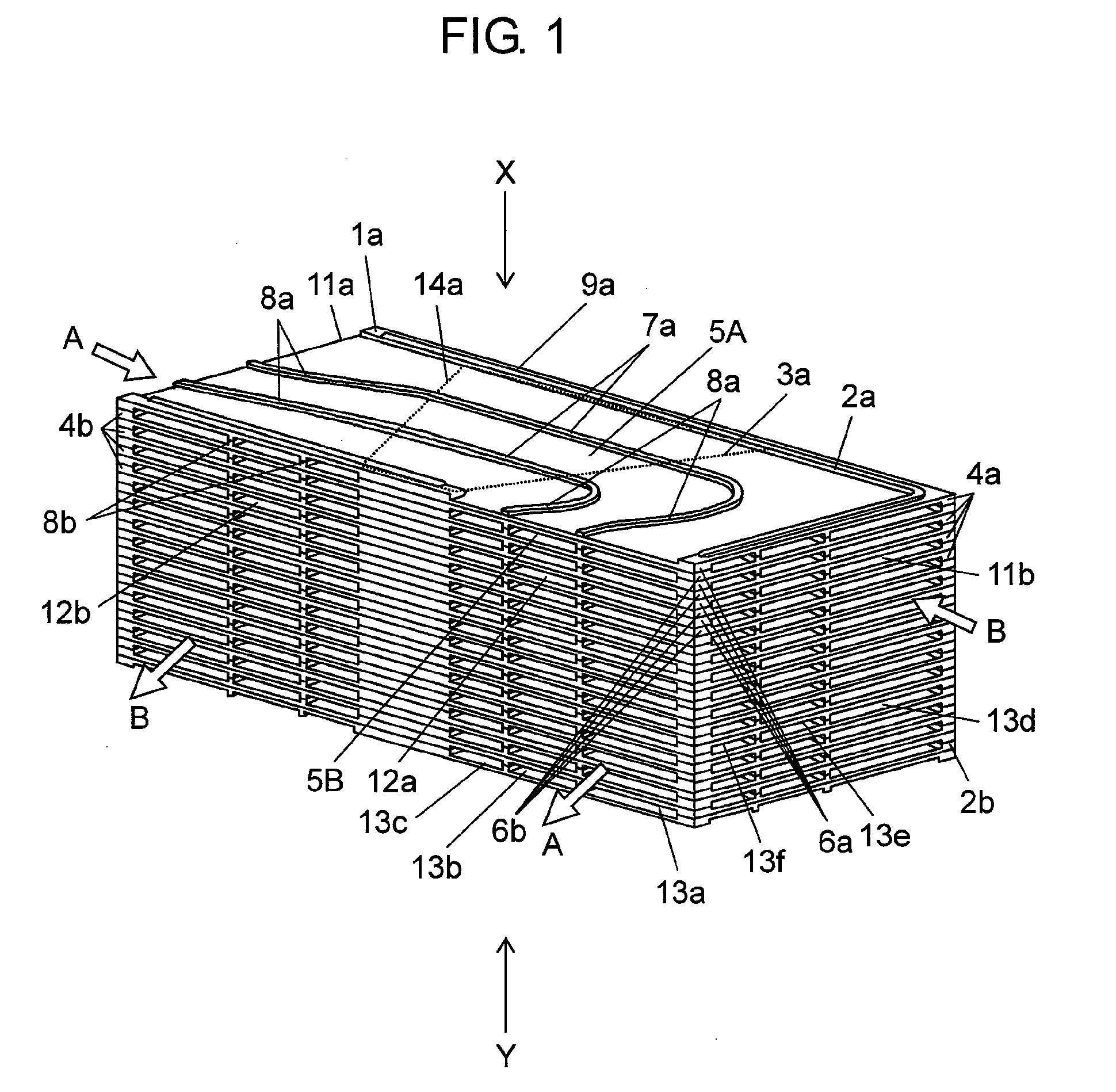
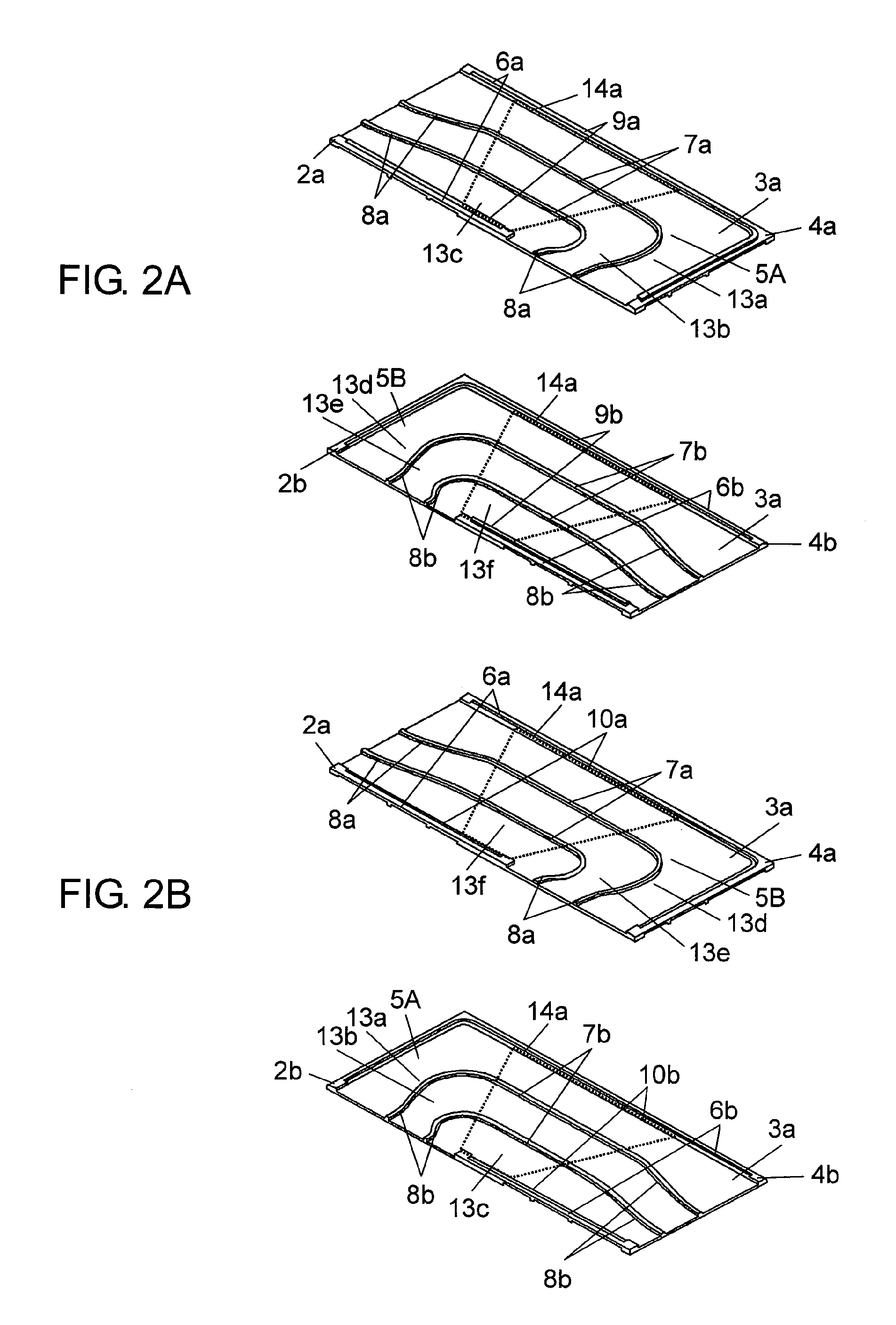
[0091]FIG. 1 is a schematic perspective view of a heat exchanging element according to a first embodiment of the present invention. FIG. 2A is a schematic perspective view of one unit element as a component of the heat exchanging element seen in a direction X of FIG. 1. FIG. 2B is a schematic perspective view of one unit element as a component of the heat exchanging element seen in a direction Y of FIG. 1. FIG. 3 is a schematic production flowchart of the heat exchanging element.

[0092]As shown in FIGS. 1, 2A, and 2B, heat exchanging element 1a includes unit elements 4a and unit elements 4b alternately laminated on each other. Each unit element 4a includes heat exchanger plate 3a integrally molded with resin frame 2a. Each unit element 4b includes heat exchanger plate 3a integrally molded with resin frame 2b. Each heat exchanger plate 3a includes air passage 5A on its top surface and air passage 5B on its bottom surface. Heat exchanging element 1a circulates primary airflow “A” throu...

second embodiment

[0116]FIG. 4 is a schematic perspective view of a heat exchanging element according to a second embodiment of the present invention. FIG. 5A is a schematic perspective view of one unit element as a component of the heat exchanging element seen in a direction X of FIG. 4. FIG. 5B is a schematic perspective view of one unit element as a component of the heat exchanging element seen in a direction Y of FIG. 4. Like components are labeled with like reference numerals with respect to the first embodiment, and these components are not described again in detail.

[0117]As shown in FIGS. 4, 5A, and 5B, heat exchanging element 1b according to the second embodiment includes unit elements 4c and unit elements 4d alternately laminated on each other. Each unit element 4c includes heat exchanger plate 3b integrally molded with resin frame 2c. Each unit element 4d includes heat exchanger plate 3b integrally molded with resin frame 2d. Each heat exchanger plate 3b includes air passage 5C on its top s...

third embodiment

[0141]FIG. 6 is a schematic perspective view of a heat exchanging element according to a third embodiment of the present invention. FIG. 7 is a schematic perspective view of one unit element as a component of the heat exchanging element seen in a direction X of FIG. 6. FIG. 8 is a schematic production flowchart of the heat exchanging element. Like components are labeled with like reference numerals with respect to the first and second embodiments, and these components are not described again in detail.

[0142]As shown in FIGS. 6 and 7, heat exchanging element 1c includes unit elements 4e and unit elements 4f alternately laminated on each other. Each unit element 4e includes shield portions 6e, flow channel division portions 7e, rectification portions 8e, and spaced projections 19a, which are formed by providing an uneven surface structure on heat exchanger plate 3c. Each unit element 4f includes shield portions 6f, flow channel division portions 7f, rectification portions 8f, and spac...


PUM


Abstract

A lamination type heat exchanging element for use in heat exchange type ventilators and other air conditioning devices eliminates drift in the air passages while maintaining its structural strength, thereby providing high heat exchange efficiency. The heat exchanging element also prevents airflow leakage due to peeling between heat exchanger plates and other components. To achieve this, rectification portions are provided which eliminate drift in the air passages due to different ventilation resistances of the flow channels caused by their different flow channel lengths generated by flow channel division portions, thereby forming a predetermined flow velocity distribution in the counterflow regions.

Description

TECHNICAL FIELD[0001]The present invention relates to a lamination type heat exchanging element for use in heat exchange type ventilation fans for domestic use, in heat exchange type ventilators for buildings and other structures, and in other air conditioning devices.BACKGROUND ART[0002]A conventional heat exchanging element is described as follows with reference to FIGS. 12A and 12B. FIG. 12A is a schematic perspective view of a conventional heat exchanger. FIG. 12B is a partial sectional view of the conventional heat exchanger.[0003]As shown in FIG. 12A, conventional heat exchanger 101 includes pairs of plates 102, each pair being opposite to and predeterminedly spaced from each other. Between each pair of plates 102 is arranged planer fin 104 having a corrugated cross section so as to form parallel flow channels 103. Adjacent pairs of plates 102 are spaced by spacers 105 for guiding primary airflow “M” and secondary airflow “N”. Heat exchanger 101 further includes space portions...

Claims


Application Information

Patent Timeline
IPC IPC(8): F28F3/08
CPCF24F12/006F28D9/0037Y02B30/563F28F13/06F28F2240/00F28F3/048F28F2250/108Y02B30/56F28F3/04F28D9/00
Inventor SUGIYAMA, MAKOTOMURAYAMA, TAKUYA
Owner PANASONIC CORP
Why Eureka
Try Eureka