Die, system, and method for coextruding a plurality of fluid layers

Inactive Publication Date: 2010-03-25
CRYOVAC INC
View PDF66 Cites 37 Cited by
  • Summary
  • Abstract
  • Description
  • Claims
  • Application Information

AI Technical Summary

Benefits of technology

[0015]Another aspect of the invention is directed to a system for coextruding a plurality of fluid layers, comprising a die

Problems solved by technology

Unfortunately, it has proven to be difficult to combine the flow of thin layers, such as microlayers, with relatively thick layers in such a way that the physical integrity and independent pro

Method used


Image

  • Die, system, and method for coextruding a plurality of fluid layers
  • Die, system, and method for coextruding a plurality of fluid layers
  • Die, system, and method for coextruding a plurality of fluid layers

Examples


Embodiment Construction

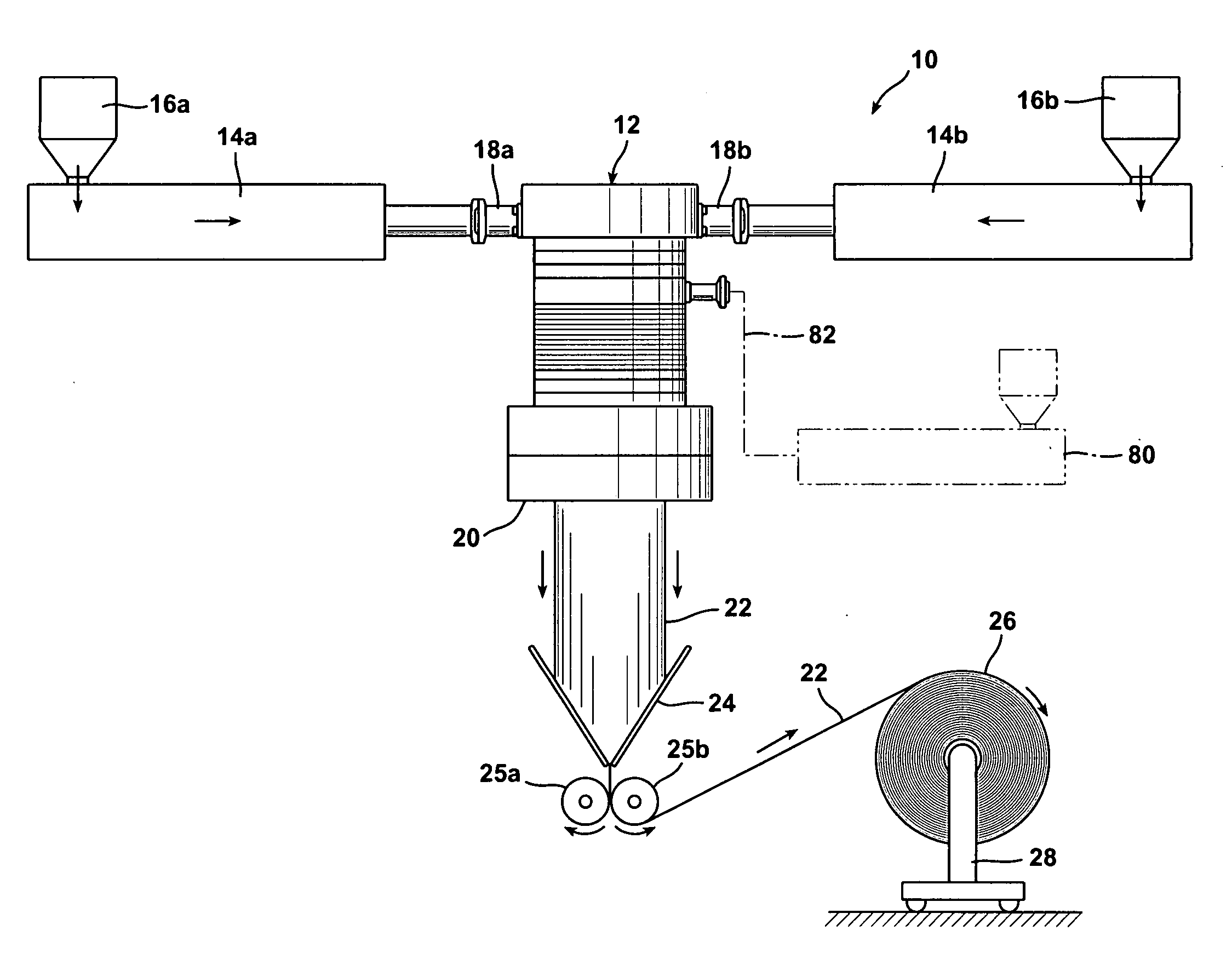
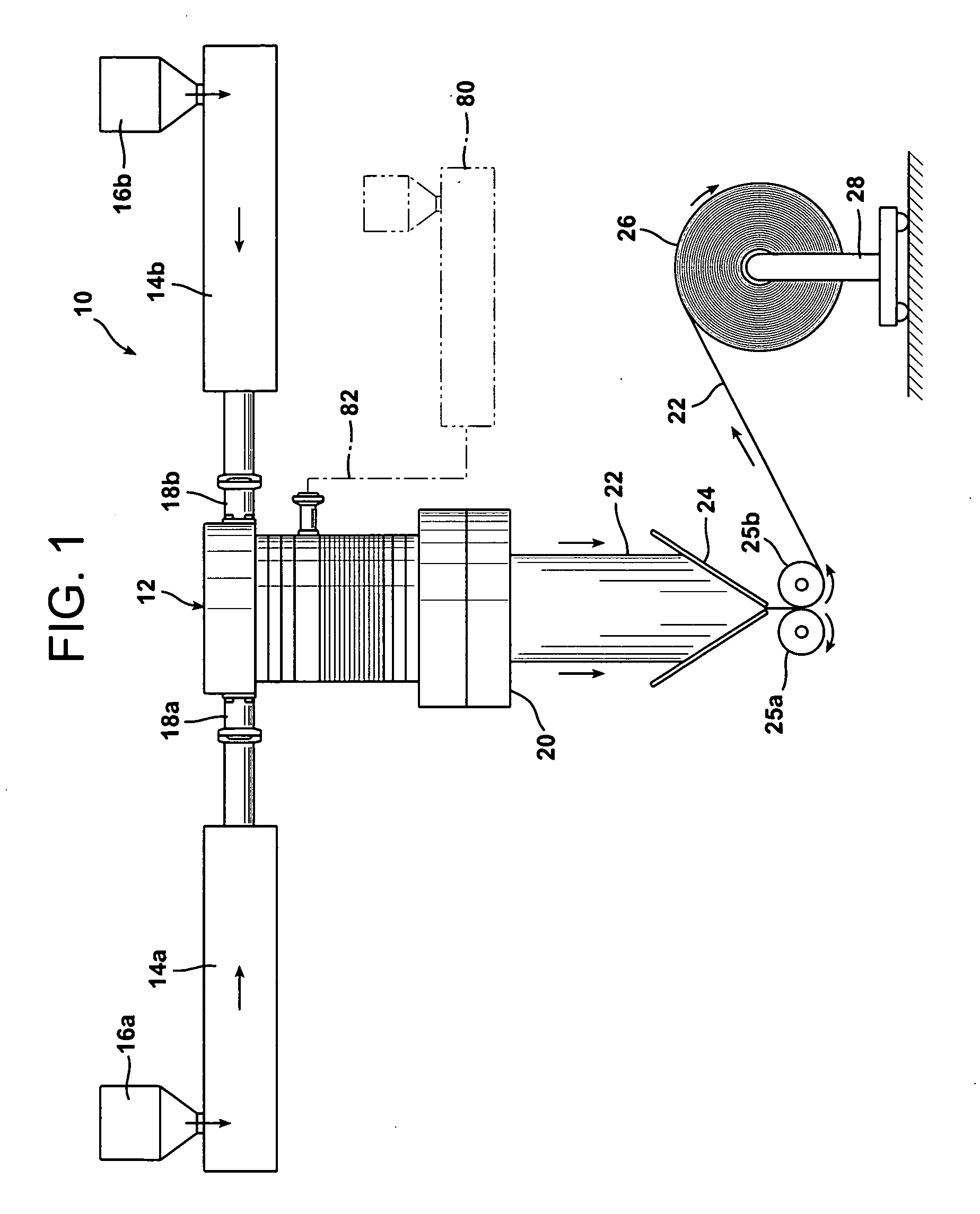
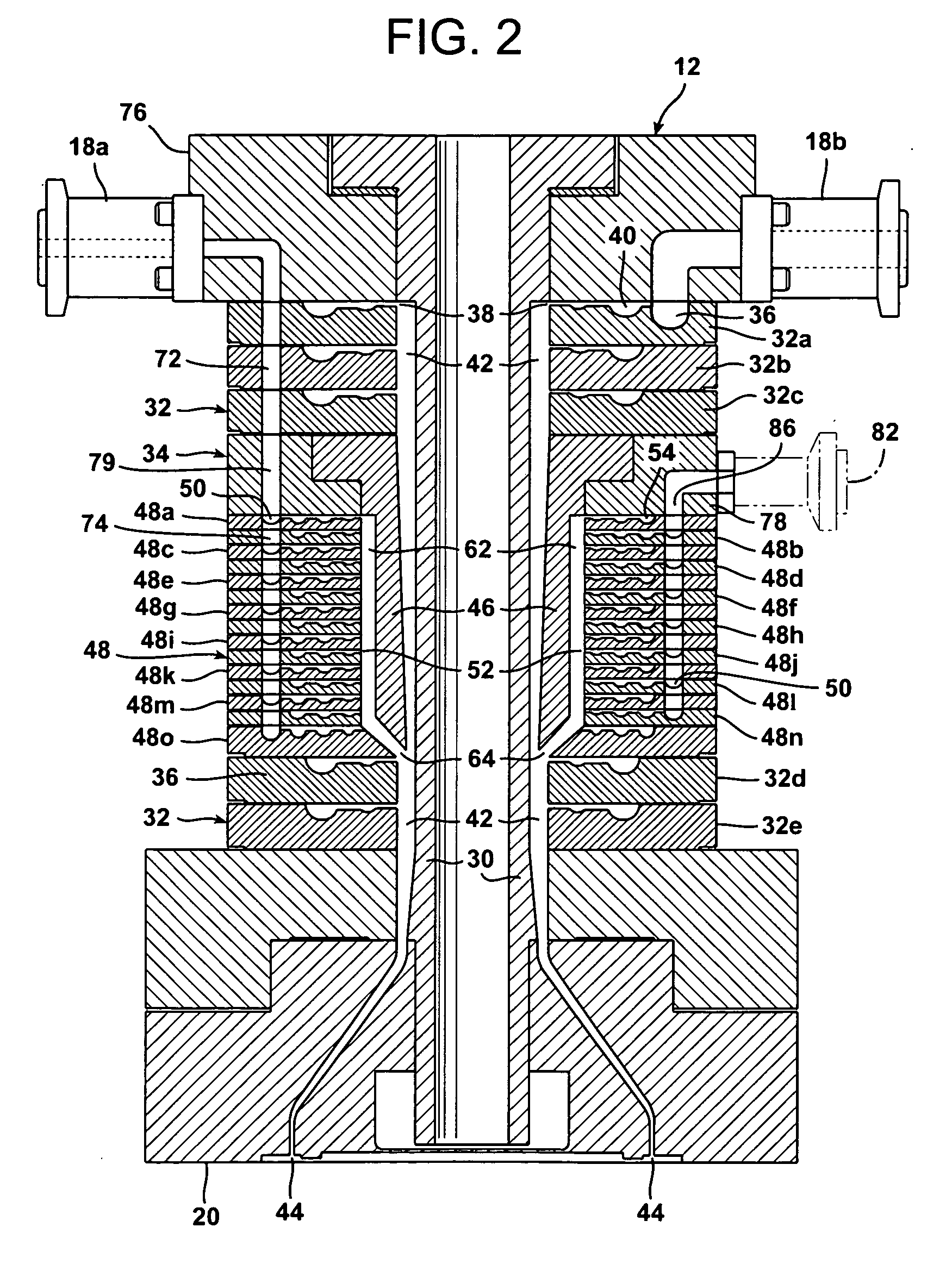
[0026]FIG. 1 schematically illustrates a system 10 in accordance with the present invention for coextruding a plurality of fluid layers. System 10 generally includes a die 12 and one or more extruders 14a and 14b in fluid communication with the die 12 to supply one or more fluids to the die.

[0027]In a typical application, the fluid layers coextruded by die 12 may comprise one or more molten thermoplastic polymers. Examples of such polymers include polyolefins, polyesters (e.g., PET), polystyrenes, polyamide homopolymers and copolymers (e.g. PA6, PA12, PA6 / 12, etc.), polycarbonates, etc. Within the family of polyolefins, various polyethylene homopolymers and copolymers may be used, as well as polypropylene homopolymers and copolymers (e.g., propylene / ethylene copolymer). Polyethylene homopolymers may include low density polyethylene (LDPE) and high density polyethylene (HDPE). Suitable polyethylene copolymers may include a wide variety of polymers, such as, e.g., ionomers, ethylene / v...


PUM

PropertyMeasurementUnit
Thicknessaaaaaaaaaa
Thicknessaaaaaaaaaa
Thicknessaaaaaaaaaa

Abstract

A die for coextruding a plurality of fluid layers generally includes a primary forming stem, one or more distribution plates, and a microlayer assembly. The microlayer assembly includes a microlayer forming stem and a plurality of microlayer distribution plates.

Description

BACKGROUND OF THE INVENTION[0001]The present invention relates to a coextrusion die and, more particularly, to a coextrusion die containing both a microlayer assembly and one or more distribution plates to produce coextruded films having both microlayers and thicker, conventional film layers.[0002]Coextrusion is a technique for producing a multilayer plastic (polymeric) film by bringing two or more molten polymers together in a die, in which the polymers are formed into a generally tubular or planar shape, juxtaposed in layered form, and then pushed out of an annular- or slot-shaped opening in the die. Once outside of the die, the still-molten multilayer film is exposed to an environment having a temperature that is maintained below the melting point of the component polymeric layers of the film, which causes the layers to melt-bond together as they cool and solidify.[0003]Multilayer films typically have a thickness in the range of 50-200 mils upon emergence from the die, but the fi...

Claims


Application Information

Patent Timeline
IPC IPC(8): B29C47/06B29C48/30B29C48/305B29C48/32B29C48/335
CPCB29C47/0021B29C47/128B29C47/0026B29C47/0057B29C47/0059B29C47/009B29C47/061B29C47/065B29C47/20B29C47/263B29C47/56B29C2791/007B29K2023/06B29K2023/0608B29K2023/0616B29K2023/0625B29K2023/0633B29K2023/0641B29K2023/065B29K2023/083B29K2023/086B29K2023/12B29K2025/00B29K2067/00B29K2069/00B29K2077/00B29C47/06B29D23/00B29C47/145B29C47/0023B29C48/09B29C48/10B29C48/18B29C48/21B29C48/32B29C48/49B29C48/185B29C48/304B29C48/307B29C48/1472B29C48/3363B29C48/08B29C48/0018B29C48/0019
Inventor ROBERTS, LAWRENCE E.TIMMONS, ANTON L.WEBSTER, BRADFORD E.
Owner CRYOVAC INC
Why Eureka
Try Eureka