
Methods and devices comprising flexible seals, flexible microchannels, or both for modulating or controlling flow and heat

a technology of flexible seals and microchannels, applied in the direction of lighting and heating apparatus, process and machine control, instruments, etc., can solve the problems of instability near certain operating conditions, difficult or problematic prior art methods for modulating and controlling flow and heat, and substantial increase in pressure drop inside the thin film

Inactive Publication Date: 2007-04-19
RGT UNIV OF CALIFORNIA +1
View PDF3 Cites 21 Cited by
  • Summary
  • Abstract
  • Description
  • Claims
  • Application Information

AI Technical Summary

Benefits of technology

[0010] The present invention provides several devices for modulating flow and heat. Several devices provided herein reduce the temperature as the thermal load increases as related to electronic cooling and cooling of engine applications. Several devices provided herein reduce the flow rate as the thermal load increases which are important to internal combustion applications where fuel rate needs to be reduced as the engine gets overheated. Several devices provided herein conserve thermal energy as the temperature increases and to reduce leakage from microfluidics. These devices have applications related to thermal insulations and biosensor devices among others.

Problems solved by technology

Unfortunately, the prior art methods for modulating and controlling the flow and heat are difficult or problematic.
For example, a two phase flow in a microchannel is capable of removing maximum heat fluxes generated by electronic packages, but instability occurs near certain operating conditions.
Further, the use of porous medium for cooling electronic devices enhances heat transfer via the increase in the effective surface area, but the porous medium results in a substantial increase in the pressure drop inside the thin film.

Method used


Image

  • Methods and devices comprising flexible seals, flexible microchannels, or both for modulating or controlling flow and heat
  • Methods and devices comprising flexible seals, flexible microchannels, or both for modulating or controlling flow and heat
  • Methods and devices comprising flexible seals, flexible microchannels, or both for modulating or controlling flow and heat

Examples


example 1

Design of Enhancements in Thermal Characterstics of Different Insulating Assemblies Utilizing Expandable Fluid Layers

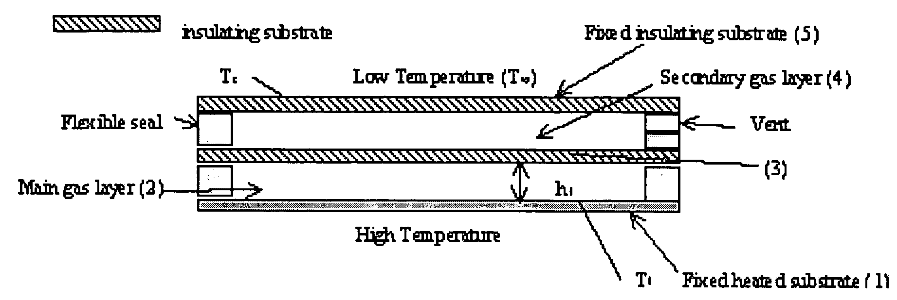
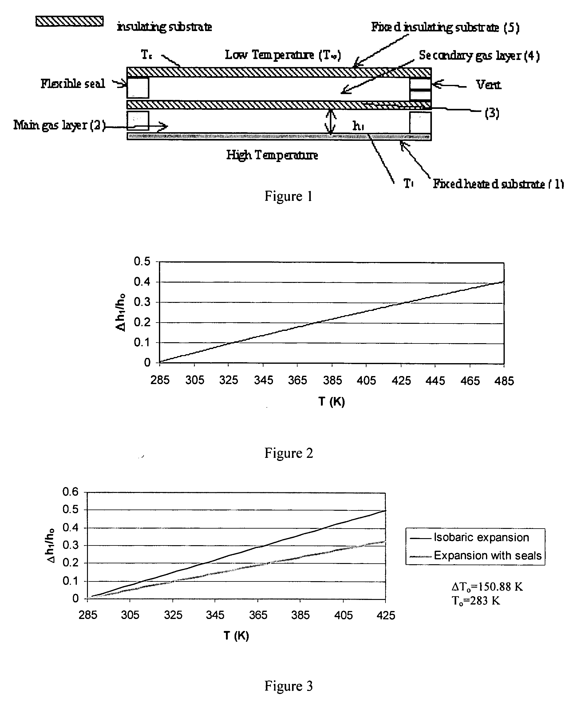
[0402] Generally, thermal losses increase at large working temperatures. The present invention provides an insulating assembly having desirable insulative attributes at high working temperatures. That is, its effective thermal resistance increases with an increase in the working temperatures. An example of an insulating assembly of the present invention is shown in FIG. 1 and is composed of the following from bottom to top: (1) a heated substrate, (2) a layer of fluid that has a very low thermal conductivity such as xenon (the primary fluid layer), (3) a thin layer of an insulating substrate, (4) a secondary fluid layer of another fluid that has a lower thermal conductivity like air (needs to be larger than that of the first layer and is open to the outside environment), and (5) a top insulating substrate. The substrates forming the fluid layers along with the interm...

example 2

Design of Enhancements in Heat Transfer Inside Expandable Thin Film Channel Supported by Flexible Complex Seals

[0406]FIG. 36 shows a thin film having a flexible complex seal. It is composed of the coolant flow, the working fluid, passage and the sealing assembly. This assembly contains closed cavities filled with a stagnant fluid having a relatively large coefficient of volumetric thermal expansion. The sealing assembly contains also flexible seals in order to allow the thin film to expand. A candidate for the flexible seal is the closed cell rubber foam. See Friis et al. (1988) J. Materials Science 23:4406-4414, which is herein incorporated by reference. Any excessive heat transfer to the thin film increases the temperature of the substrate. Thus, the stagnant fluid becomes warmer and expands. The seals are flexible enough so that the expansion results in an increase in the separation between the lower and the upper substrates. Accordingly, the flow resistance of the working fluid...

example 3

Design of the Control of Flow and Thermal Exit Conditions Using Two-Layered Thin Films Supported by Flexible Complex Seals

[0415] Two-layered thin films possess enhanced cooling capacity. See Vafai & Zhu (1999) Int. J. Heat and Mass Transfer 42:2287-2297, which is herein incorporated by reference. These two-layered systems also provide a passive control of flow and exit thermal conditions for the main thin film when flexible complex seals are separating the substrates of the two-layered thin film as shown in FIG. 25. This figure shows that the lower layer contains the primary fluid flow passage where its lower substrate is fixed (immobile and inflexible substrate) and its upper substrate is free to move in the vertical direction (mobile and inflexible substrate). The flow in the primary fluid layer can be that of the fuel or fuel-air mixture prior to combustion or flow of a biofluid in a fluidic cell. The upper layer of the thin film contains a secondary fluid flow parallel or count...


PUM


Abstract

Disclosed herein are devices comprising at least one flexible seal, at least one flexible complex seal having at least one closed cavity containing a fluid, or a combination thereof. The devices may comprise at least one immobile and inflexible substrate and at least one mobile and inflexible substrate capable of movement due to the flexible seal, the flexible complex seal, or both. The flexible complex seals comprise at least one closed cavity comprising a fluid, such as a gas or a liquid. As disclosed, the presence or absence of heat will cause the mobile and inflexible substrate to move. The movement will increase or decrease the fluid amount or fluid flow rate in the primary fluid layer. Also disclosed are methods for enhancing the insulating properties of insulating assemblies.

Description

CROSS-REFERENCE TO RELATED APPLICATIONS [0001] This application is a continuation-in-part of U.S. patent application Ser. No. 10 / 840,303, filed 7 May 2004, pending, which claims the benefit of U.S. Provisional Patent Application No. 60 / 470,850 filed 16 May 2003, which names Kambiz Vafai and Abdul Rahim A. Khaled as inventors, which are herein incorporated by reference in their entirety.BACKGROUND OF THE INVENTION [0002] 1. Field of the Invention [0003] The present invention generally relates to thin film channels, microfluidic devices, biosensors, electronic cooling, control of fuel flow prior combustion and insulating assemblies. [0004] 2. Description of the Related Art [0005] Thin films are used in a variety of devices, including electrical, electronic, chemical, and biological devices, for modulating or controlling flow and heat characteristics in the devices. See e.g. Vafai & Wang (1992) Int. J. Heat Mass Transfer 35:2087-2099, Vafai et al. (1995) ASME J Heat Transfer 117:209-21...

Claims


Application Information

Patent Timeline
Patent Type & Authority Applications(United States)
IPC IPC(8): G05D23/02G05D23/13F16J15/00B01J19/00F16J15/02
CPCF28F2230/00B01J2219/00783B01J2219/00804B01J2219/00864B01J2219/00873B82Y30/00F23C2900/03001F23N2900/01001F28F3/10F28F3/12F28F13/00B01J19/0093G05D23/02F16J15/064
Inventor VAFAI, KAMBIZKHALED, ABDUL RAHIM A.
Owner RGT UNIV OF CALIFORNIA
Learn More