
Method of forming a pattern using nano imprinting and method of manufacturing a mold to form such a pattern

Active Publication Date: 2010-03-25
SAMSUNG ELECTRONICS CO LTD
View PDF11 Cites 21 Cited by
  • Summary
  • Abstract
  • Description
  • Claims
  • Application Information

AI Technical Summary

Benefits of technology

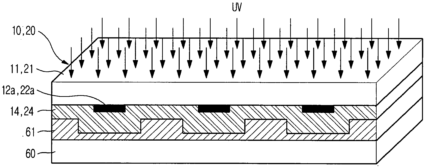
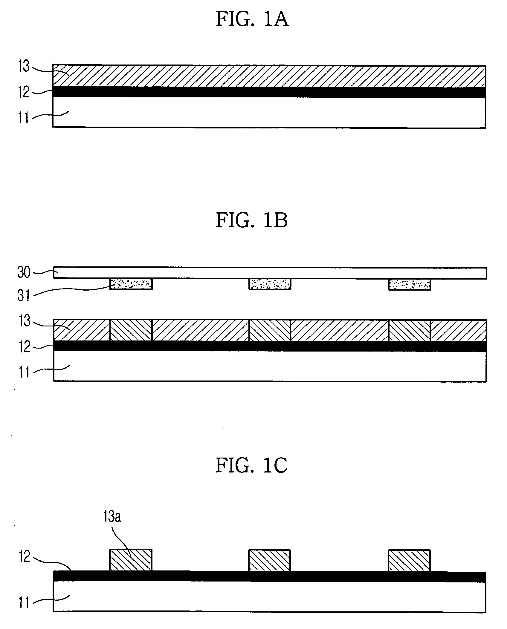
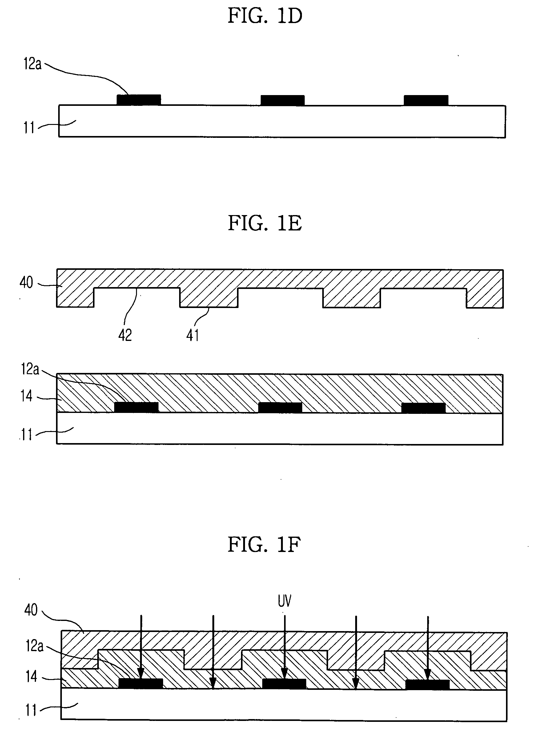
[0008]Example embodiments relate to a method of forming a multi-step pattern (three-dimensional pattern) using a one-step shaped mold and a method of manufacturing a mold to form such a pattern. As a result, the manufacture of a multi-step shaped mold may be avoided, thus simplifying the method of forming a multi-step pattern.

Problems solved by technology

However, the conventional technology for forming such a mold may be relatively complicated and difficult, thus involving increased process costs and time.
For instance, a multi-step shaped mold for nano imprinting may be necessary to form a relatively complicated three-dimensional micro pattern or a multi-step pattern, but it may be relatively difficult to manufacture the multi-step shaped mold.

Method used


Image

  • Method of forming a pattern using nano imprinting and method of manufacturing a mold to form such a pattern
  • Method of forming a pattern using nano imprinting and method of manufacturing a mold to form such a pattern
  • Method of forming a pattern using nano imprinting and method of manufacturing a mold to form such a pattern

Examples


Embodiment Construction

[0019]It will be understood that when an element or layer is referred to as being “on,”“connected to,”“coupled to,” or “covering” another element or layer, it may be directly on, connected to, coupled to, or covering the other element or layer or intervening elements or layers may be present. In contrast, when an element is referred to as being “directly on,”“directly connected to,” or “directly coupled to” another element or layer, there are no intervening elements or layers present. Like numbers refer to like elements throughout the specification. As used herein, the term “and / or” includes any and all combinations of one or more of the associated listed items.

[0020]It will be understood that, although the terms first, second, third, etc. may be used herein to describe various elements, components, regions, layers, and / or sections, these elements, components, regions, layers, and / or sections should not be limited by these terms. These terms are only used to distinguish one element,...


PUM

PropertyMeasurementUnit
Sizeaaaaaaaaaa
Adhesion strengthaaaaaaaaaa
Moldableaaaaaaaaaa

Abstract

Example embodiments relate to a method of forming a three-dimensional micro pattern or a multi-step pattern using a nano imprinting process and a method of manufacturing a mold to form such a pattern. A molding polymer may be patterned in a one-step shape on a substrate having UV barrier patterns, thereby easing the manufacture of a mold for multi-step imprinting and simplifying the formation of a multi-step pattern using the one-step shaped mold by avoiding the repetition of more complicated processes. Consequently, it may be possible to form a relatively large-area micro pattern, a relatively large-area pattern usable in flat panel displays, and a nano pattern having a size of several tens of nanometers in a semiconductor process, thereby contributing to the reduction of process costs, the reduction of process time, and the improvement of production yield.

Description

CROSS-REFERENCE TO RELATED APPLICATION[0001]This application claims priority under 35 U.S.C. §119 to Korean Patent Application No. 2008-0092430, filed on Sep. 19, 2008 with the Korean Intellectual Property Office, the entire disclosure of which is incorporated herein by reference.BACKGROUND[0002]1. Field[0003]Example embodiments relate to a method of forming a three-dimensional micro pattern or a multi-step pattern using a nano imprint process and a method of manufacturing a mold to form such a pattern.[0004]2. Description of the Related Art[0005]A nano imprint process to form a pattern having a nano size of about 1 to 100 nm using a mold may be classified as a thermal type process or an ultraviolet (UV) type process. The nano imprint process may be applicable to a plastic substrate (which may require a relatively low-temperature process) and a glass or quartz substrate (which may exhibit no conductivity) as well as a semiconductor substrate (e.g., a silicon (Si) substrate).[0006]Th...

Claims


Application Information

Patent Timeline
IPC IPC(8): B29C35/08B29C33/06
CPCB82Y10/00G03F7/0002B82Y40/00
Inventor CHO, YOUNG TAESIM, YOUNG SUKKIM, JEONG GIL
Owner SAMSUNG ELECTRONICS CO LTD
Learn More