Wheel suspension for motor vehicles
- Summary
- Abstract
- Description
- Claims
- Application Information
AI Technical Summary
Benefits of technology
Problems solved by technology
Method used
Image

Examples
second embodiment
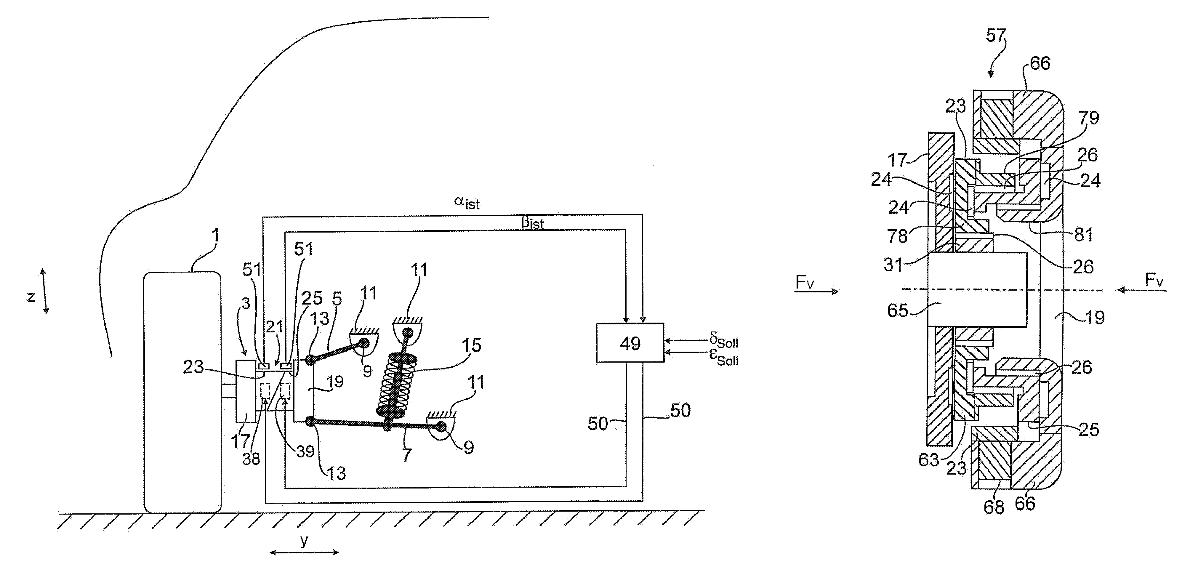
[0045]In the second embodiment as shown in FIG. 5, the pretensioning means is designed as a universal joint 57 which is connected between the wheel-side support member 17 and the axle-side support member 19.
[0046]The embodiment shown in FIG. 5 in fundamental structure matches the preceding embodiment. In this respect, reference is made to its description. In contrast to the preceding embodiments, the vehicle wheel 1 which is held on the wheel-side support member 17 is not trailed, i.e., is not driven by an articulated shaft, but there is additionally an articulated shaft 58 which is shown by the broken line in FIG. 5.
[0047]The articulated shaft 58 is routed through the cavities 35 of the two pivoted parts 23, 25 and drives the vehicle wheel 1, as is the case for a rear wheel or all wheel drive. For reasons of space therefore the two actuating drives 38, 39 (in FIG. 5 only the actuating drive 39 is shown) are no longer located within the cavities 35, but outside the cavity 35 of the ...
third embodiment
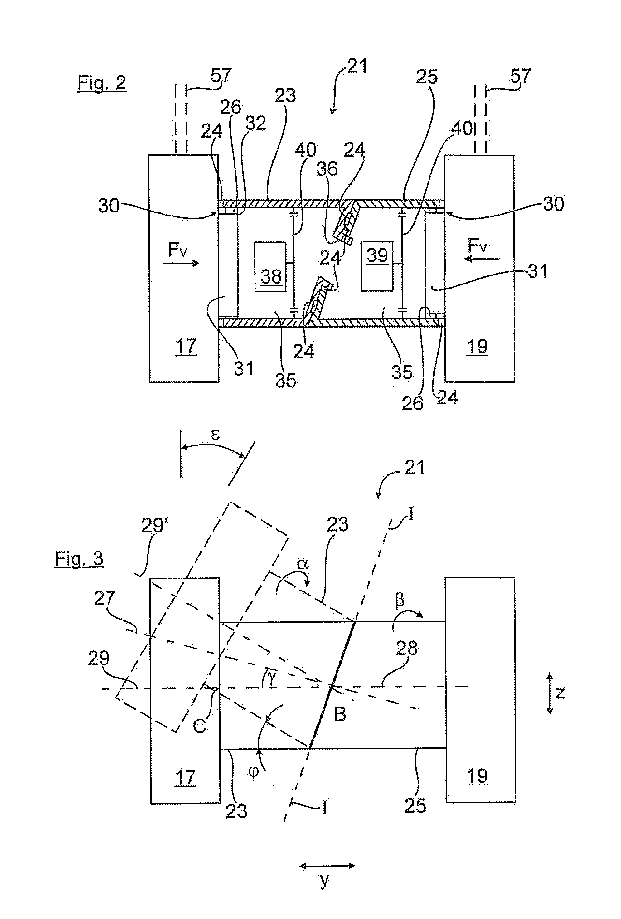
[0052]FIG. 6 shows a technical implementation of the wheel suspension shown in FIG. 5. The structure and the method of operation of the wheel suspensions shown in FIGS. 5 and 6 are essentially the same. Thus the wheel suspension shown in FIG. 6 likewise has two wheel-side and axle-side support members 17, 19. The wheel-side support member 17 is inserted with the central axle projection 31 into the hub section 78 of the wheel-side pivoted part 23. The hub section 78 is spaced radially apart from the cylindrical outside wall 79 of the pivoted part 23 by way of an annular gap. The hollow cylindrical pivoted part 25 whose tilted end side is in contact with the corresponding gap base of the pivoted part 23 by way of the axial needle bearing 24 projects into the annular gap between the cylindrical outside wall 79 and the hub section 78. The pivoted part 25 with its inside periphery sits on a hub section 81 of the axle-side support member 19 with the interposition of a radial needle beari...
PUM
 Abstract
Description
Claims
Application Information
 - Generate Ideas
- Intellectual Property
- Life Sciences
- Materials
- Tech Scout
- Unparalleled Data Quality
- Higher Quality Content
- 60% Fewer Hallucinations
Browse by: Latest US Patents, China's latest patents, Technical Efficacy Thesaurus, Application Domain, Technology Topic, Popular Technical Reports.
© 2025 PatSnap. All rights reserved.Legal|Privacy policy|Modern Slavery Act Transparency Statement|Sitemap|About US| Contact US: help@patsnap.com