Liquid crystal display device and video display device using the same

a display device and liquid crystal technology, applied in the direction of color television details, television systems, instruments, etc., can solve the problems of bringing the light source, the need for a certain amount of space, and the end of the display region may experience light unevenness, so as to suppress the light unevenness

Active Publication Date: 2010-03-25
MAXELL HLDG LTD
View PDF2 Cites 51 Cited by
  • Summary
  • Abstract
  • Description
  • Claims
  • Application Information

AI Technical Summary

Benefits of technology

[0011]According to the present invention, it is possible to provide the liquid crystal display device and the

Problems solved by technology

That is, light unevenness may occur at the end of a display region.
Additionally, in view of the deflection caused by the thermal deformation of the light guide plate 9, it is difficult to bring the light source 14 into contact with the light guide plate 9, and thus there is a need for a

Method used


Image

  • Liquid crystal display device and video display device using the same
  • Liquid crystal display device and video display device using the same
  • Liquid crystal display device and video display device using the same

Examples


first embodiment

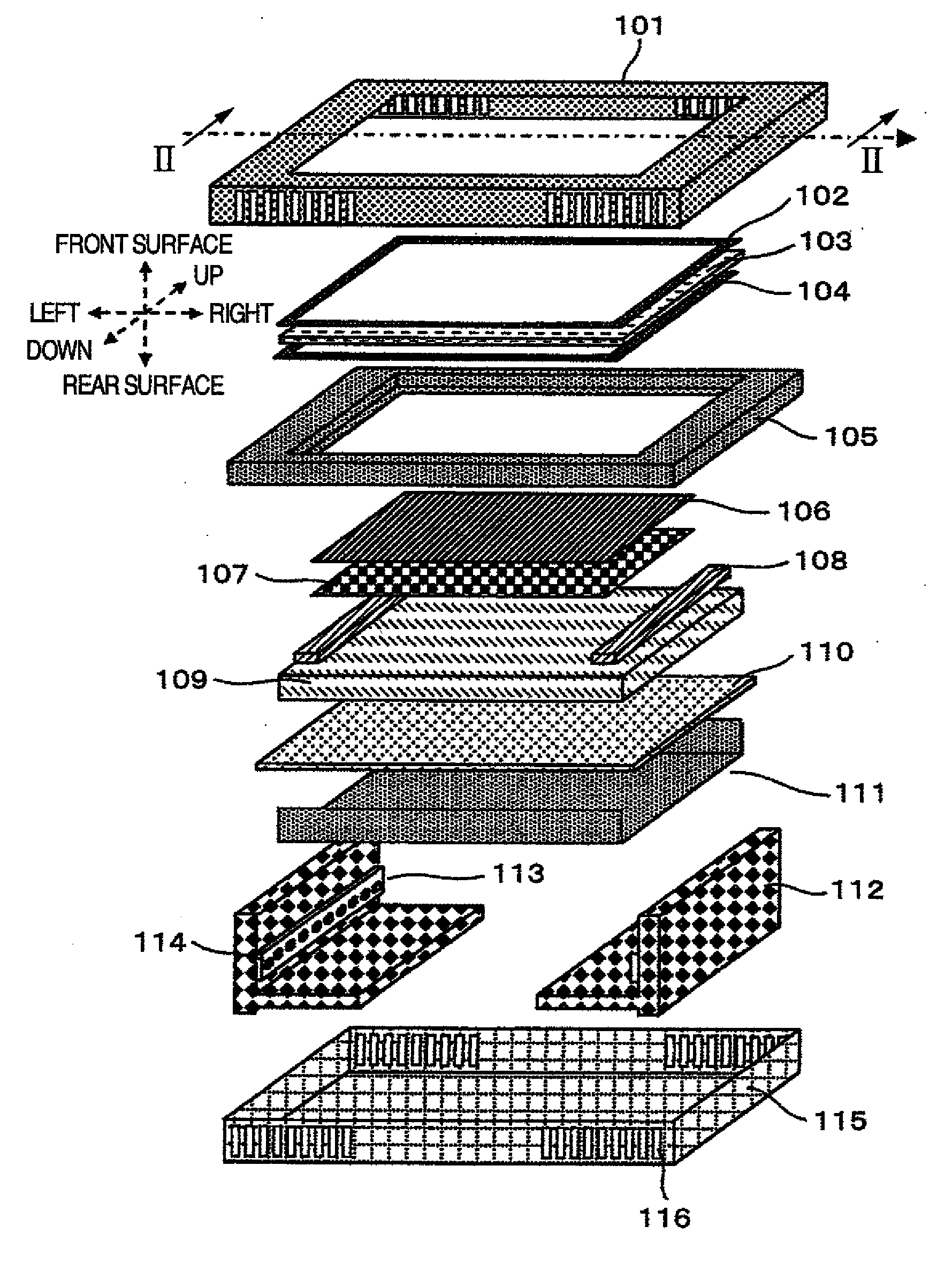
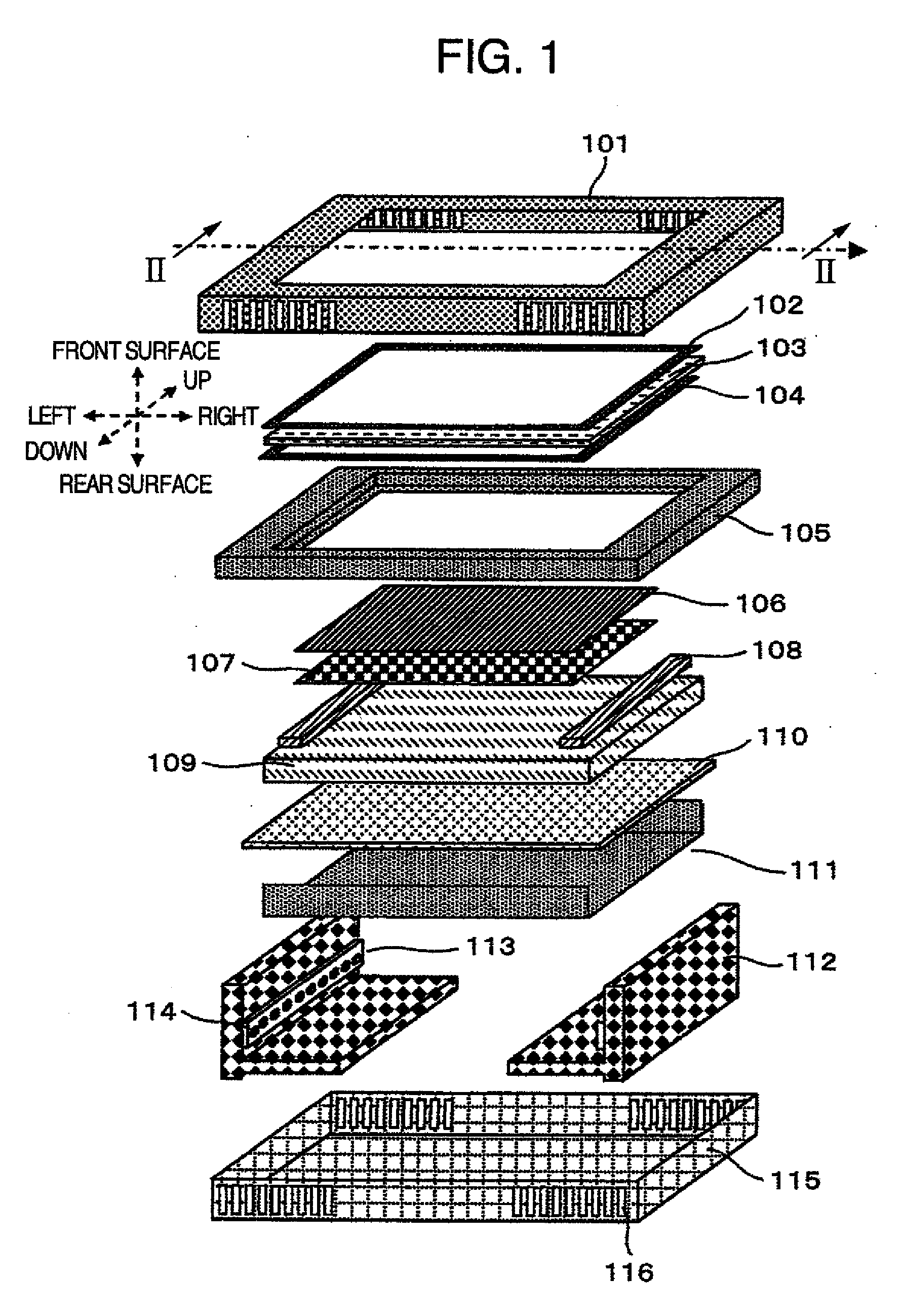
[0025]FIG. 1 is a perspective view illustrating a liquid crystal display device according to a first embodiment of the invention. As shown in FIG. 1, vertical and horizontal directions, and front and rear surfaces are defined on the basis of a display screen of a liquid crystal panel 103 in the present embodiment. The liquid crystal display device according to the present embodiment is provided with a first frame 101, a first rubber cushion 102, a liquid crystal panel 103, a second rubber cushion 104, a liquid crystal support member 105, a first optical sheet 106, a second optical sheet 107, a cushion member 108, a light guide plate 109, a lower reflection sheet 110, a second frame 111, a heat sink 112, a light source mounting substrate 113, a light source 114, and a rear surface cover 115. The light guide plate 109 is disposed on the rear surface of the liquid crystal panel 103. The light source mounting substrate 113 is disposed on either side surface of the light guide plate 109....

second embodiment

[0044]A second embodiment according to the present invention will be described in detail with reference to FIG. 9.

[0045]Except a portion where the upper reflection sheet 201 is disposed between the cushion member 108 and the light guide plate 109, the present embodiment is substantially equal to the first embodiment. Since the cushion member 108 is made of an elastic material, the gap between the light guide plate 109 and the upper reflection sheet 201 is not opened, so that it is possible to prevent the light from leakage. For example, such a cushion member 108 includes (1) the acrylate resin material of which the carbon number of the side chain is four or more, (2) a material which is made by adding a plasticizer made of dibutyl phthalate or the like to the acrylate resin having one to three of the carbon number of the side chain, or (3) a chloroprene rubber, a silicon rubber, or fluorine series rubber which are excellent in the heat resistance and the weather resistance.

[0046]The...


PUM


Abstract

In a liquid crystal display device and a video display device using the same, for suppressing light unevenness at the end of a display region, the video display device is provided with a liquid crystal display device and a housing configured to support the liquid crystal display device, wherein the liquid crystal display device includes a liquid crystal panel, a first frame and a liquid crystal support member which interpose the liquid crystal panel therebetween, a light guide plate which is disposed at the liquid crystal support member on a side opposite to a side where the liquid crystal panel is disposed, and a light source which is disposed at a side surface of the light guide plate, and wherein a cushion member is disposed between the liquid crystal support member and the light guide plate.

Description

FIELD OF THE INVENTION[0001]The present invention relates to a liquid crystal display device and a video display device using the same.DESCRIPTION OF RELATED ART [0002]A video display device is generally classified into a luminous video display device, such as a CRT (Cathode Ray Tube), a plasma display panel, or the like, and a non-luminous video display device, such as a liquid crystal display device, or the like. As the non-luminous video display device, there are a device in which a reflection type optical modulation element is used to adjust an amount of reflected light according to an image signal, and a device in which a transmissive optical modulation element is used to adjust an amount of transmitted light according to the image signal. In particular, the liquid crystal display device which uses a liquid crystal display panel as the transmissive optical modulation element and is provided with an illuminating device (also refer to as a backlight) on a rear surface thereof is ...

Claims


Application Information

Patent Timeline
IPC IPC(8): H04N5/64G02F1/1333
CPCG02F1/133308G02F2201/503G02F2001/133317G02F1/133317
Inventor KONNO, AKITOYOSASAKI, HIROSHISATO, KATSUNARI
Owner MAXELL HLDG LTD
Why Eureka
Try Eureka