Planar illumination device and liquid crystal display device using the same

a technology of liquid crystal display and illumination device, which is applied in the direction of lighting and heating apparatus, instruments, mechanical equipment, etc., can solve the problems of insufficient number of optical fibers, increased power consumption, and inability to elaborate, so as to reduce the noise of output light, accurate uniformity, and low power consumption

Inactive Publication Date: 2010-03-25
PANASONIC CORP
View PDF5 Cites 40 Cited by
  • Summary
  • Abstract
  • Description
  • Claims
  • Application Information

AI Technical Summary

Benefits of technology

[0015]In this planar illumination device, the laser light from the laser light source is transmitted to the light guide plate without almost any loss via the light source side bundle fiber, the light guiding member and the plurality of connection side fibers, incident on the lig

Problems solved by technology

However, since power consumption has also been increased as screens have become larger, technological development for realizing lower power consumption is hoped for and it is strongly demanded to thin display devices in order to maximally reduce indoor spaces taken up by display devices.
However, in the prior arts described above, it is proposed to realize thinner planar illumination devic

Method used


Image

  • Planar illumination device and liquid crystal display device using the same
  • Planar illumination device and liquid crystal display device using the same
  • Planar illumination device and liquid crystal display device using the same

Examples


first embodiment

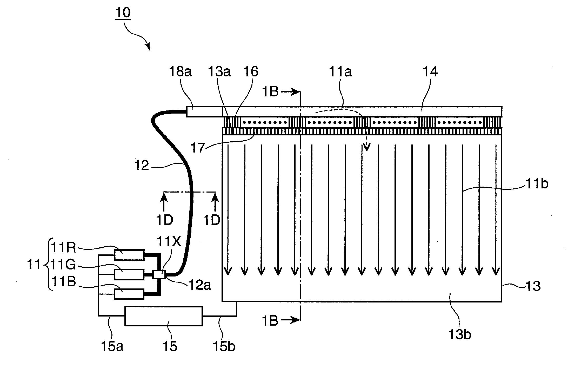
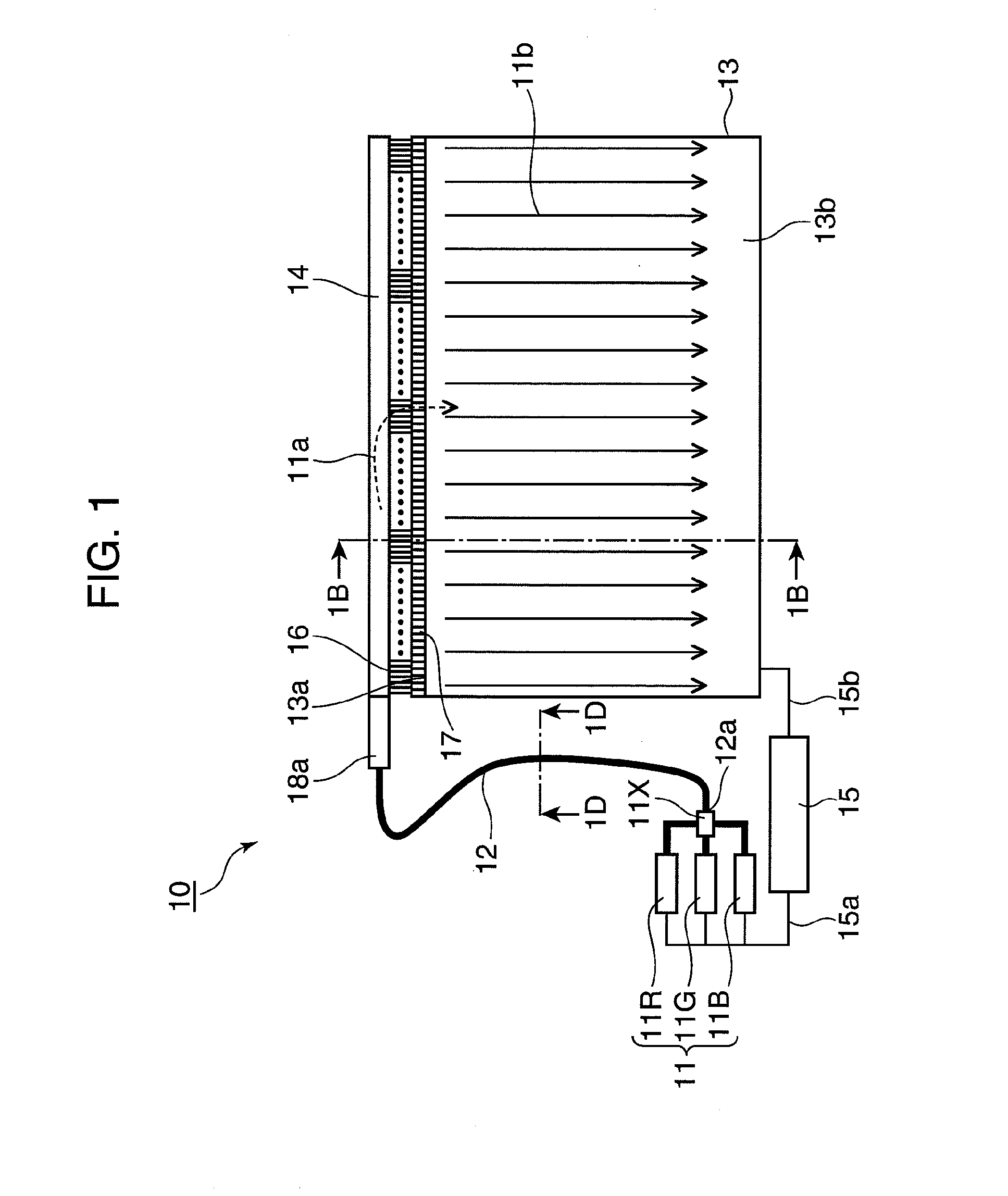
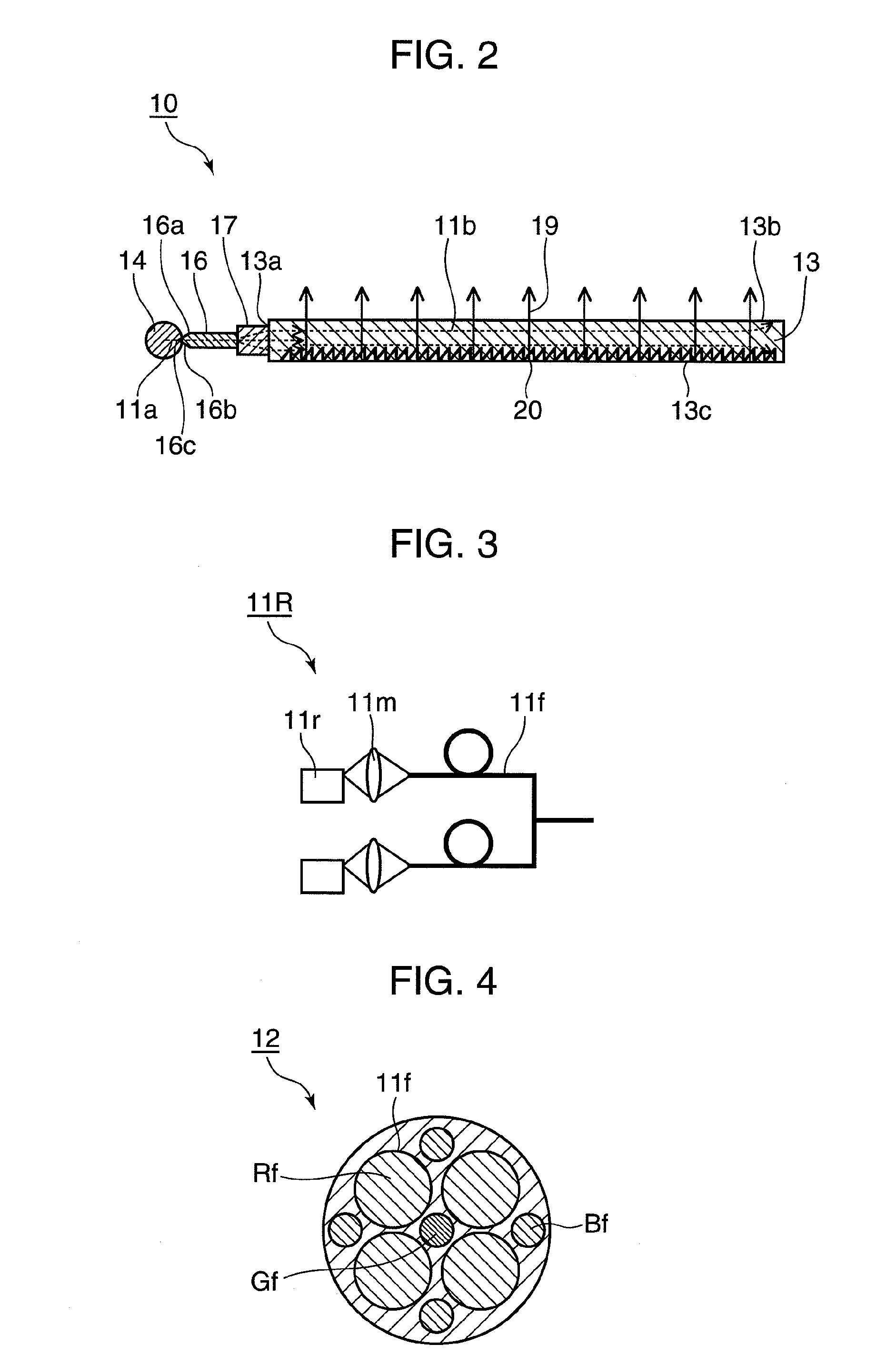
[0033]FIGS. 1 and 2 are schematic construction diagrams of a planar illumination device 10 according to a first embodiment of the present invention, wherein FIG. 1 is a plan view diagrammatically showing the entire construction of the planar illumination device 10 and FIG. 2 is a section of the planar illumination device 10 along 1B-1B of FIG. 1. FIG. 3 is a diagram showing a construction example of a laser light source 11 of the planar illumination device 10 shown in FIG. 1, and FIG. 4 is a section of a light source side bundle fiber 12 along ID-ID of FIG. 1. Although the respective parts of the planar illumination device 10 are shown to be separated in order to facilitate the understanding of the respective constructions in FIG. 1, they are placed on or within an unillustrated base plate or a frame in an actual construction to be entirely and integrally fixed.

[0034]As shown in FIGS. 1 and 2, the planar illumination device 10 according to this embodiment is provided with a laser li...

second embodiment

[0064]FIGS. 8 and 9 are schematic construction diagrams of a planar illumination device 30 according to a second embodiment of the present invention, wherein FIG. 8 is a plan view diagrammatically showing the entire construction of the planar illumination device 30 and FIG. 9 is a section of the planar illumination device 30 along 2B-2B of FIG. 8. Although the respective parts of the planar illumination device 30 are shown to be separated in order to facilitate the understanding of the respective constructions in FIG. 8, they are placed on or within an unillustrated base plate or a frame in an actual construction to be entirely and integrally fixed.

[0065]As shown in FIGS. 8 and 9, the planar illumination device 30 of this embodiment differs from the planar illumination device 10 of the first embodiment in that one principal surface 13b of a light guide plate 13 is enclosed by a pair of shorter sides 31a and a pair of longer sides 31b facing each other and connection side fibers 16 a...

third embodiment

[0069]FIG. 10 is a plan view showing a schematic construction of a planar illumination device 40 according to a third embodiment of the present invention. Although the respective parts of the planar illumination device 40 are shown to be separated in order to facilitate the understanding of the respective constructions also in FIG. 10, they are placed on or within an unillustrated base plate or a frame in an actual construction to be entirely and integrally fixed.

[0070]The planar illumination device 40 of this embodiment shown in FIG. 10 differs from the planar illumination devices 10, 30 of the first and second embodiments in the constructions of the laser light source 11, the light guiding fiber 14 and the connection side fibers 16. In other words, the light guiding fiber 14 is comprised of a plurality of branch light guiding fibers 14a, 14b, 14c and 14d and the planar illumination device 40 of this embodiment further includes an optical switch element 43 having the opposite sides...


PUM


Abstract

A planar illumination device 10 is provided with a laser light source 11 for emitting laser light, a light source side bundle fiber 12 having one end surface thereof optically connected with the laser light source 11, a flat light guide plate 13, a plurality of connection side fibers 16 planarly arranged in parallel with each other at a side surface of the light guide plate 13, and a light guiding fiber 14 for guiding the laser light from the light source side bundle fiber 12 to the plurality of connection side fibers 16. The laser light is incident on the side surface of the light guide plate 13 from the plurality of connection side fibers 16 via a plurality of fiber collimators 17 and output light is uniformly emitted from one principal surface of the light guide plate 13.

Description

BACKGROUND OF THE INVENTION[0001]1. Field of Technology[0002]The present invention relates to a high-luminance planar illumination device using a laser light source and used in a non-emissive display device such as a liquid crystal television and a liquid crystal display device using the same.[0003]2. Description of the Background Art[0004]A liquid crystal display device adopts a method for displaying an image by controlling a transmission amount of light irradiated from behind utilizing an electrooptic effect by the orientation of liquid crystal molecules and generally requires a planar illumination device called a backlight unit formed by fluorescent display tubes. In recent years, screens of such liquid crystal display devices have become larger and display devices for televisions of 50 inches and larger have been put to practical use. However, since power consumption has also been increased as screens have become larger, technological development for realizing lower power consum...

Claims


Application Information

Patent Timeline
IPC IPC(8): G02F1/13357F21V7/04F21V8/00
CPCG02B6/0028G02B6/0038G02F1/133615G02B6/04G02B6/0068
Inventor ITOH, TATSUOSHIKII, SHINICHINAGATA, TAKAYUKIYAMAMOTO, KAZUHISA
Owner PANASONIC CORP
Why Eureka
Try Eureka