Zoom lens and imaging apparatus

a zoom lens and imaging apparatus technology, applied in the field of wide-angle zoom lenses, can solve the problems of reducing operability during focusing, increasing lateral chromatic aberration and distortion, etc., and achieves the effects of small size, high focus performance, and small variation in performan

Inactive Publication Date: 2010-03-25
FUJI PHOTO OPTICAL CO LTD
View PDF9 Cites 7 Cited by
  • Summary
  • Abstract
  • Description
  • Claims
  • Application Information

AI Technical Summary

Benefits of technology

[0007]The invention has been made in order to solve the above-mentioned problems, and an object of the invention is to provide a zoom lens capable of achieving an optical system having a small size, a zoom ratio of 2 or more at a wide angle, and a small variation in performance when power varies, and an imaging apparatus. Another object of the invention is to provide a zoom lens having high focus performances, such as a light-weight focus group and a small variation in performance during focusing, in addition to a high zoom performance, and an imaging apparatus.

Problems solved by technology

In this structure, lateral chromatic aberration and distortion are increased.
However, in the three-group zoom lens, since the first lens group has a large outside diameter and a heavy weight, the operability is lowered during focusing.

Method used


Image

  • Zoom lens and imaging apparatus
  • Zoom lens and imaging apparatus
  • Zoom lens and imaging apparatus

Examples


examples

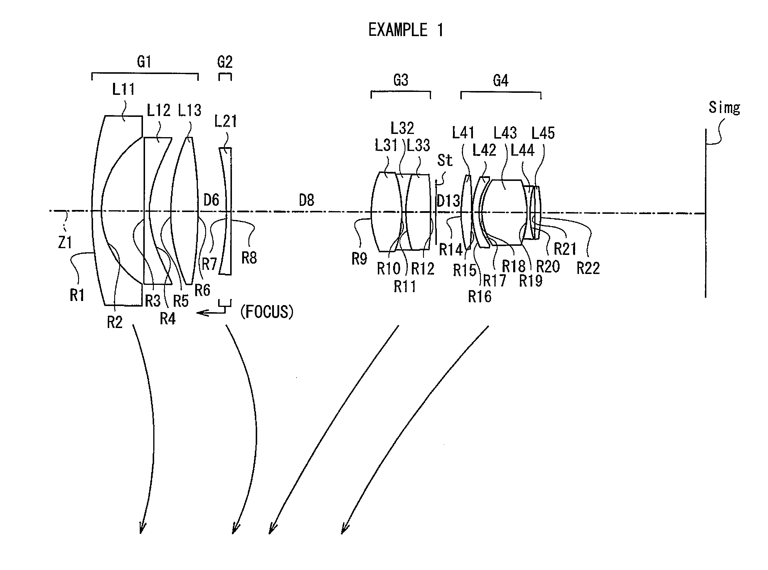
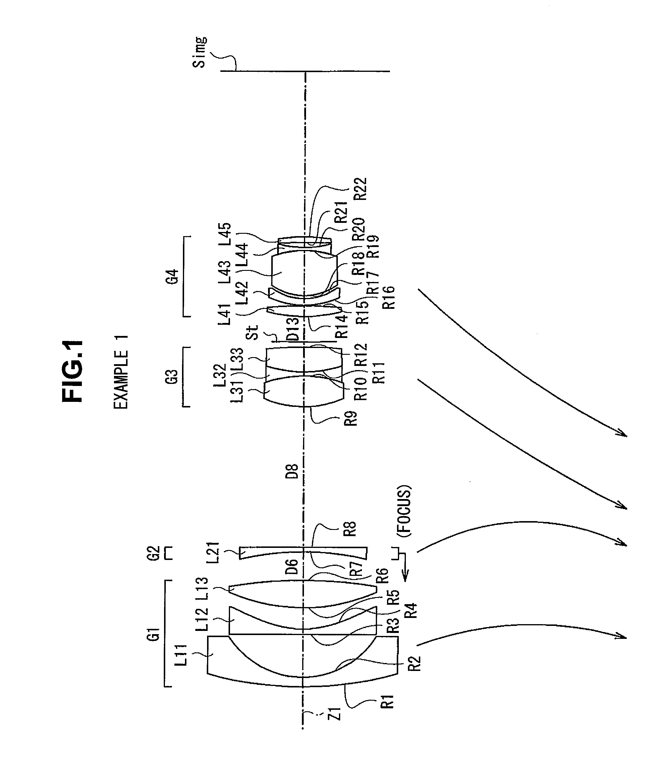
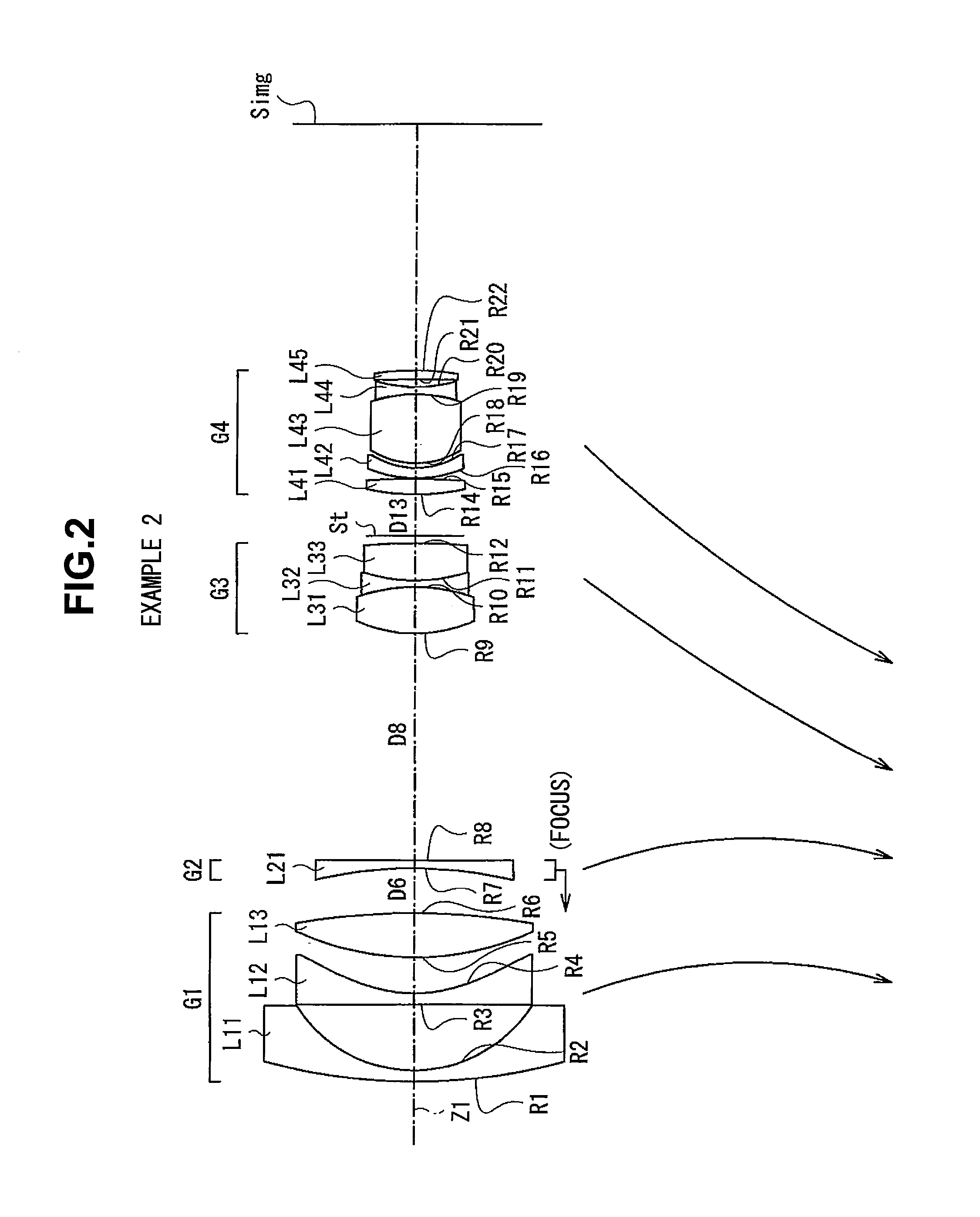
[0064]Next, detailed numerical examples of the zoom lens according to this embodiment will be described. A plurality of numerical examples will be described below.

[0065]Table 1 and Tables 2A and 2B show detailed lens data corresponding to the structure of the zoom lens shown in FIG. 1.

TABLE 1EXAMPLE 1 BASIC LENS DATASiRiDiNdjνdj(SURFACE(CURVATURE(SURFACE(REFRACTIVE(ABBENUMBER)RADIUS)SPACING)INDEX)NUMBER) 1127.6093.501.7291654.7 231.78715.45 3∞2.041.5176063.5G1 {open oversize brace} *435.0197.68 567.4319.901.8830040.8 6−163.829D6(VARIABLE) 7−100.05 1.66 1.69680 55.5G2 {open oversize brace}  8∞ D8(VARIABLE) 936.03511.301.4874970.210−41.0221.391.8340037.3G3 {open oversize brace} 1144.1059.131.7173629.512−149.4641.9813(APERTURED13(VARIABLE) DIAPHRAGM)1453.6043.951.4874970.215−144.4090.161630.8022.391.8830040.81720.341.12G4 {open oversize brace} 1820.44416.421.4970081.619−34.5481.001.7880047.42034.5481.8821−311.8422.001.9036631.322−60.125(*ASPHERIC SURFACE)

TABLE 2AEXAMPLE 1 ALL DATAWIDE ...


PUM


Abstract

A zoom lens includes a first negative lens group, a second negative lens group, a third positive lens group, an aperture diaphragm, and a fourth positive lens group arranged in this order from an object side. When power varies from a wide angle end to a telephoto end, the first and second lens groups are moved to an image surface along an optical axis and then moved to the object side. The third and fourth lens groups are moved to only the object side along the optical axis. The first lens group includes at least one aspheric lens, and the aspheric lens has an aspheric shape in which a positive refractive power is increased toward the periphery of the lens when a paraxial refractive power is positive and a negative refractive power is decreased toward the periphery of the lens when the paraxial refractive power is negative.

Description

CROSS-REFERENCE TO RELATED APPLICATIONS[0001]This application is based upon and claims the benefit of priority from the Japanese Patent Application No. 2008-241398 filed on Sep. 19, 2008; the entire contents of which are incorporated herein by reference.BACKGROUND OF THE INVENTION[0002]1. Field of the Invention[0003]The present invention relates to a wide-angle zoom lens applicable for, for example, a silver salt single lens reflex camera or a digital single lens reflex camera, and more particularly, to a zoom lens having an angle of view 2ω of more than 70° at a wide angle end, an F number of about F4 to about F5.6, and a zoom ratio of about 2.4, and an imaging apparatus including the zoom lens.[0004]2. Description of the Related Art[0005]In general, a wide-angle zoom lens for a single reflex lens requires a large back focal length. Therefore, an optical system is configured such that there is strong asymmetry in an optical axis direction. In this structure, lateral chromatic aberr...

Claims


Application Information

Patent Timeline
Patent Type & Authority Applications(United States)
IPC IPC(8): G02B15/177G02B15/16
CPCG02B15/177G02B15/144513
Inventor SUZUKI, TAKASHI
Owner FUJI PHOTO OPTICAL CO LTD
Why Eureka
Try Eureka