SSD apparatus

Inactive Publication Date: 2010-03-25
KK TOSHIBA
View PDF28 Cites 82 Cited by
  • Summary
  • Abstract
  • Description
  • Claims
  • Application Information

AI Technical Summary

Benefits of technology

[0027]FIG. 16 is a view showing a techni

Problems solved by technology

However, the above argument presupposes that the SSD apparatus is applied to a la

Method used


Image

  • SSD apparatus
  • SSD apparatus
  • SSD apparatus

Examples


embodiment

3. Embodiment

[0079](1) Overall Configuration

[0080]FIG. 5 is an exploded view of an SSD apparatus according to an embodiment of the invention.

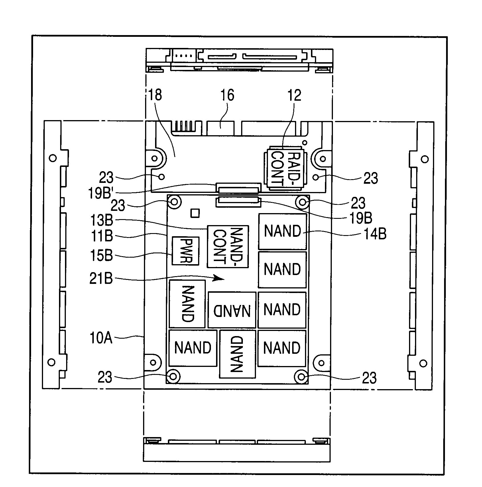
[0081]The standardized casing (for example, 1.8- or 2.5-inch size) is comprised of bottom cover 10A and top cover 10B.

[0082]In order to reduce a newly invested cost including development cost and material cost, existing units with guaranteed performance are used as they are as memory modules 21A and 21B. Namely, the configurations (for example, the components and the layouts) of memory modules 21A and 21B are the same as those of the existing units.

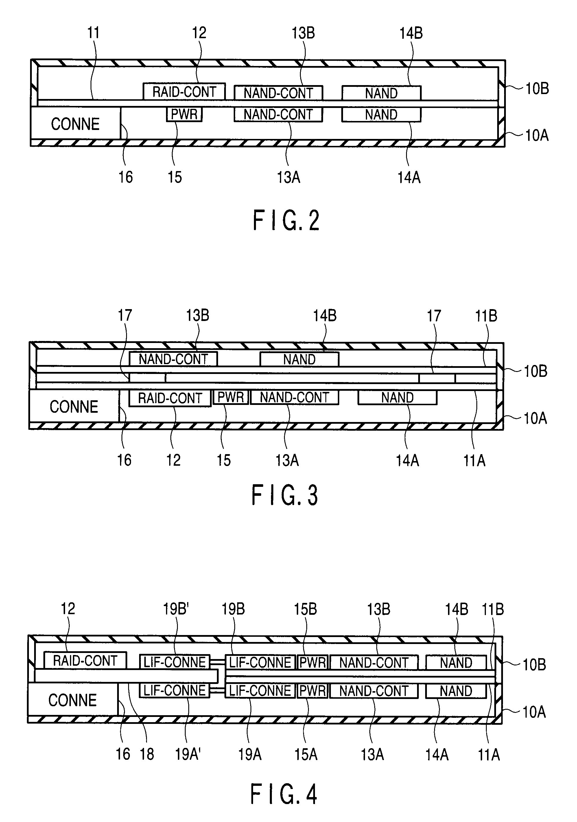
[0083]Memory module 21A includes, for example, NAND controller 13A, NAND chip 14A, and power supply chip 15A of FIG. 4. Memory module 21B includes, for example, NAND controller 13B, NAND chip 14B, and power supply chip 15B of FIG. 4.

[0084]Memory modules 21A and 21B are in a state that the other sides of the printed circuit boards, on which no chips are mounted, face each other. Insulating sheet 22 is...

application example

4. Application Example

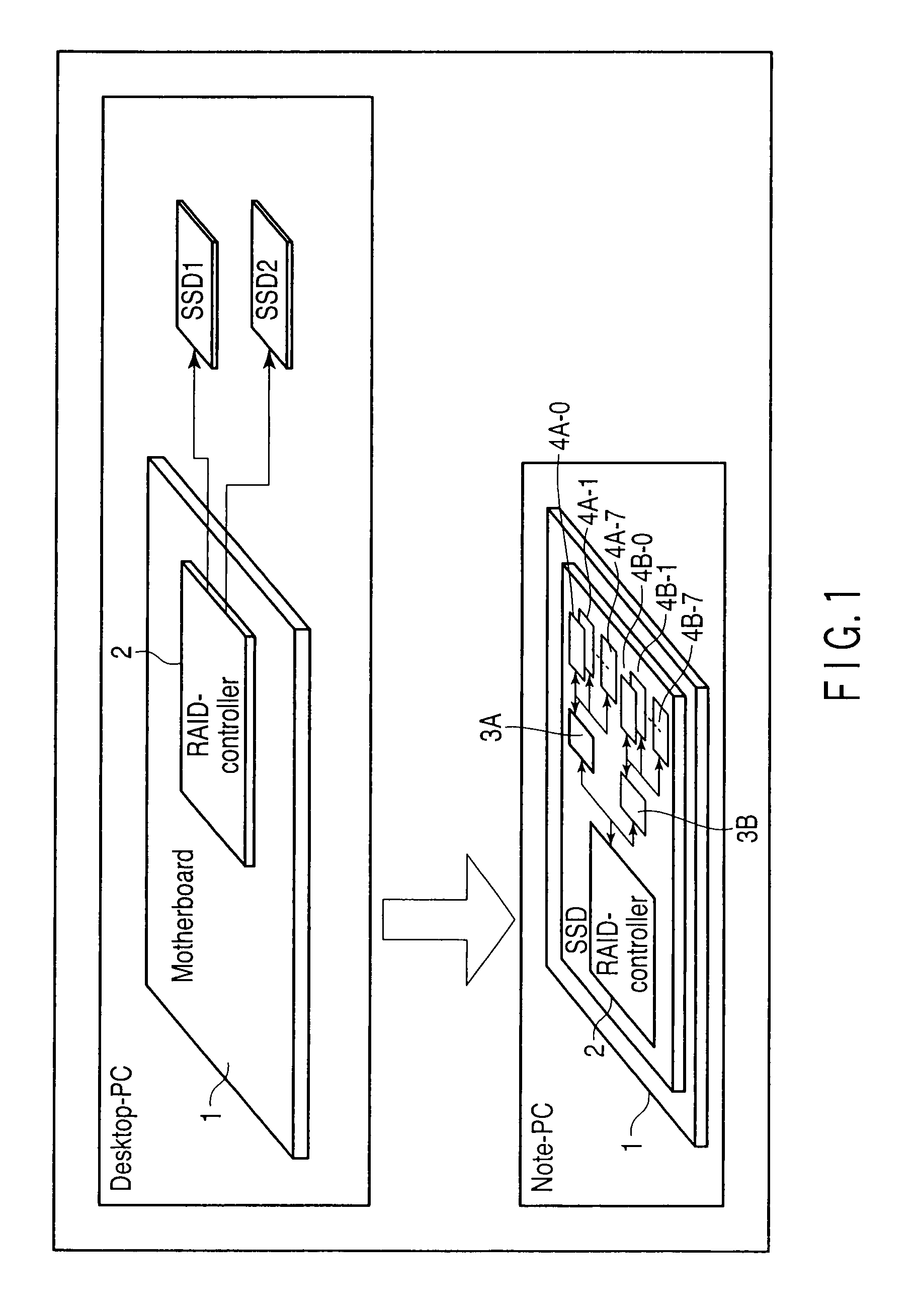
[0144]According to the SSD apparatus according to the embodiment of the invention, since the control board mounted with the RAID controller is provided separately from the printed circuit board (module board), the first and second memory modules can be comprised of an existing unit with guaranteed performance.

[0145]Therefore, the RAID system can be easily built in one SSD apparatus, and, at the same time, the SSD apparatus is not required to be redesigned from the beginning, whereby a high-quality finished product can be provided.

[0146]Further, since a design resource can be reduced, the development within a short delivery period of time can be realized. Furthermore, a conventional technique of the SSD apparatus can be diverted, and therefore, in terms of performance to cost, a high-performance product can be provided.

[0147]Furthermore, no restrictions are imposed on the interface, whereby the range of application of the SSD apparatus can be enlarged.

[0148]For ...


PUM


Abstract

A SSD apparatus includes a first memory module, a second memory module, a module controller which determines a method of controlling the first and second memory modules, a control board mounted with the module controller, a first connector which a module board of the first memory module and the control board are connected to, a second connector which a module board of the second memory module and the control board are connected to, and an interface device connected to the control board. A memory chip and a memory controller are mounted on one surface of the module board of each of the first and second memory modules. The other surface of the module board of the first memory module is faced to the other surface of the module board of the second memory module.

Description

CROSS-REFERENCE TO RELATED APPLICATIONS[0001]This application is based upon and claims the benefit of priority from prior Japanese Patent Application No. 2008-244811, filed Sep. 24, 2008, the entire contents of which are incorporated herein by reference.BACKGROUND OF THE INVENTION[0002]1. Field of the Invention[0003]The present invention relates to solid-state disk (SSD) device.[0004]2. Description of the Related Art[0005]A SSD apparatus is a large-capacity data storage device using a nonvolatile semiconductor memory such as a NAND flash memory. The SSD apparatus has an interface which is the same as a magnetic recording hard disk drive (HDD), and therefore recently has come into use in, for example, a personal computer and a server by virtue of increase in the capacity and price reduction.[0006]A method for expansive utilization of HDDs includes a Redundant Arrays of Inexpensive Disks (RAID) method (for example, see Jpn. Pat. Appln. KOKAI Publications Nos. 8-203297 and 10-284684).[...

Claims


Application Information

Patent Timeline
IPC IPC(8): H05K7/00
CPCG06F3/0626G06F3/0658G06F3/0688H01L2224/73204H01L2924/13091H01L2924/00G11C16/00H01L23/50H05K3/22
Inventor MORIAI, TAKAKATSUEGUCHI, TOYOKAZU
Owner KK TOSHIBA
Why Eureka
Try Eureka