Control voltage tracking circuits, methods for recording a control voltage for a clock synchronization circuit and methods for setting a voltage controlled delay

Active Publication Date: 2010-03-25
MICRON TECH INC
View PDF4 Cites 23 Cited by
  • Summary
  • Abstract
  • Description
  • Claims
  • Application Information

AI Technical Summary

Problems solved by technology

Moreover, the amount of time to obtain a locked timing condition will be affected by process variations in semiconductor integrated circuits (ICs).
Voltage and temperature variations also affects the performance of ICs.
When the DLL 100 is re-enabled after being

Method used


Image

  • Control voltage tracking circuits, methods for recording a control voltage for a clock synchronization circuit and methods for setting a voltage controlled delay
  • Control voltage tracking circuits, methods for recording a control voltage for a clock synchronization circuit and methods for setting a voltage controlled delay
  • Control voltage tracking circuits, methods for recording a control voltage for a clock synchronization circuit and methods for setting a voltage controlled delay

Examples


Embodiment Construction

[0015]Certain details are set forth below to provide a sufficient understanding of embodiments of the invention. However, it will be clear to one skilled in the art that embodiments of the invention may be practiced without these particular details. Moreover, the particular embodiments of the present invention described herein are provided by way of example and should not be used to limit the scope of the invention to these particular embodiments. In other instances, well-known circuits, control signals, timing protocols, and software operations have not been shown in detail in order to avoid unnecessarily obscuring the invention.

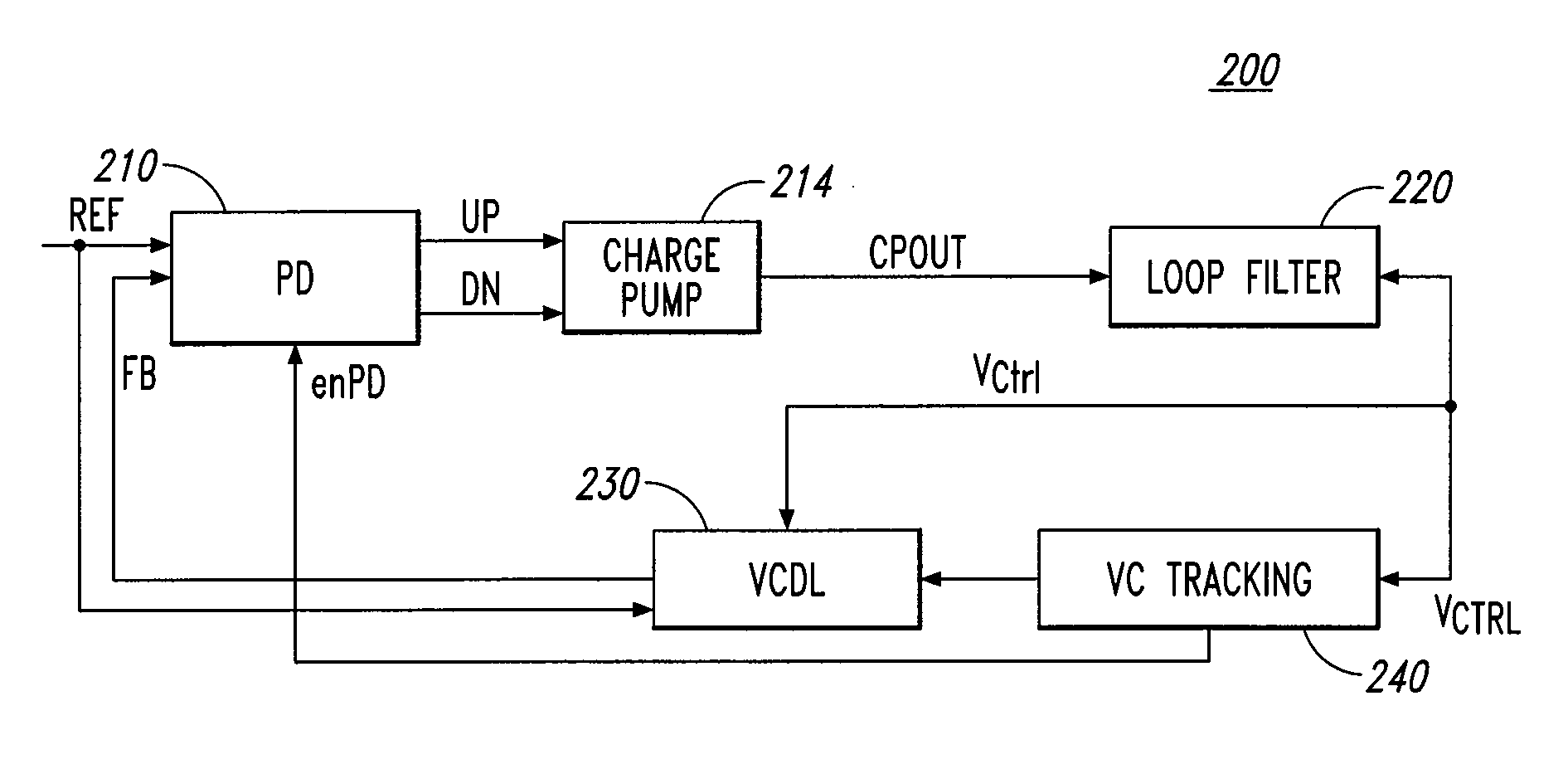
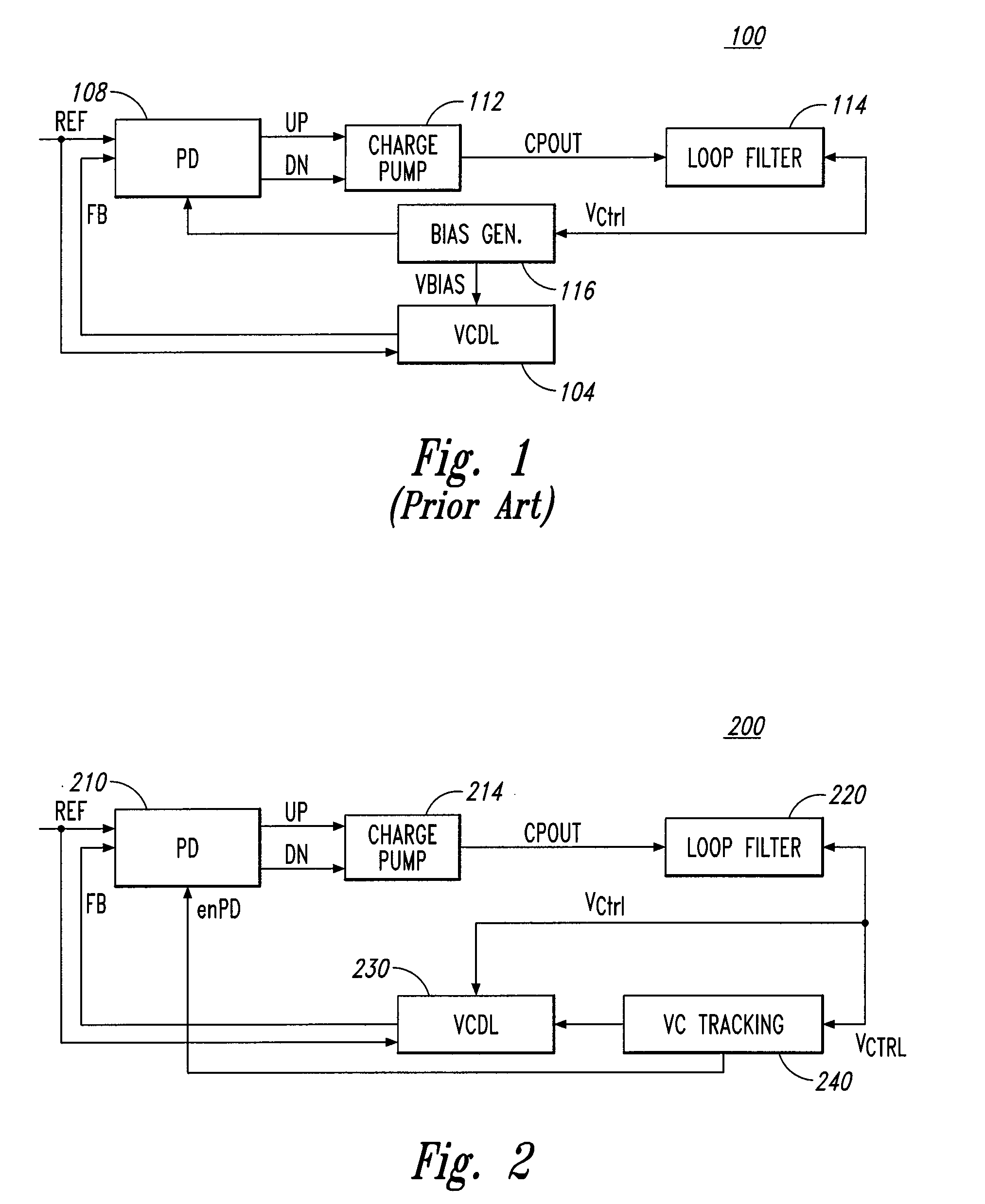
[0016]FIG. 2 illustrates a DLL 200 according to an embodiment of the invention. The DLL 200 includes a phase detector 210 that receives a reference clock signal REF and a feedback clock signal FB. The phase detector 210 determines a phase difference between the two clock signals and generates control signals, shown in FIG. 2 as UP and DN signals, for a char...


PUM


Abstract

Memories, clock synchronization circuits, clock synchronization controller circuits, and methods for setting a voltage controlled delay of a clock synchronization circuit and tracking and recording the control voltage are disclosed. For example, a clock synchronization controller provides an initial control voltage to the voltage controlled delay during initialization of the synchronization circuit until a phase dependent control voltage stabilizes. The stable phase dependent control voltage is substituted for the initial control voltage. Following stabilization of the phase dependent control voltage, a phase detector of the clock synchronization circuit is activated. A recovery control voltage is provided by the clock synchronization controller to the voltage controlled delay during recovery of the clock synchronization from a power-saving mode until the phase dependent control voltage stabilizes.

Description

TECHNICAL FIELD[0001]Embodiments of the invention relate generally to clock synchronization circuits, and in one or more particular embodiments, to circuits and methods for tracking and recording a control voltage for clock synchronization circuits.BACKGROUND OF THE INVENTION[0002]In many electronic circuits, it is necessary to generate internal clocks with predetermined phase relationships to a reference clock. Clock synchronization circuits such as phase locked loops (PLLs) or delay locked loops (DLLs) are often used to generate an internal clock signal that is synchronized, e.g., in phase, with a reference clock signal.[0003]FIG. 1 is a block diagram of a conventional DLL 100. The DLL 100 includes a voltage controlled delay line (VCDL) 104 that receives a reference clock signal REF, and in response, generates a feedback clock signal FB having a delay relative to the REF signal that is based on a voltage magnitude of a control voltage VCTRL. The DLL 100 also includes a phase detec...

Claims


Application Information

Patent Timeline
IPC IPC(8): G11C7/00H03L7/06G11C8/00
CPCG11C7/20G11C7/22G11C7/222H03L7/093G11C29/023G11C29/028H03L7/0812G11C29/02H03L7/0816
Inventor LIN, FENG
Owner MICRON TECH INC
Why Eureka
Try Eureka