Thin battery and a method of manufacturing a thin battery

a thin battery and manufacturing method technology, applied in the field of thin batteries, can solve the problems of difficult application of electrode materials, and achieve the effects of preventing short-circuiting, facilitating battery production, and preventing short-circuiting over the edges

Inactive Publication Date: 2010-03-25
ENFUCELL
View PDF20 Cites 19 Cited by
  • Summary
  • Abstract
  • Description
  • Claims
  • Application Information

AI Technical Summary

Benefits of technology

[0041]The main benefit of the invention is that the use of multiple papers in the separator layer makes the production of the battery easier than the methods used in prior art. The earlier mentioned wet strength problems in the prior art methods with wet cathode and anode layers can be avoided by means of the invention.
[0042]In addition to the production benefit, the multiple paper structure makes the risk of short circuiting smaller. This is based on both experience and on the theory that zinc needles that are formed in the anode do not penetrate several layers of paper as easily as they penetrate one layer. The main benefit, however, in preventing short-circuiting lies in that, as the intermediate separator layer(s) are bigger in area, the short-circuiting over the edges is prevented.

Problems solved by technology

In addition to the above mentioned problem of short-circuiting over the edges, another problem in traditional manufacturing methods to overcome is that the paper sheets become quite wet when they are impregnated with the electrolyte, which makes the application of the electrode materials difficult.

Method used


Image

  • Thin battery and a method of manufacturing a thin battery
  • Thin battery and a method of manufacturing a thin battery
  • Thin battery and a method of manufacturing a thin battery

Examples


Embodiment Construction

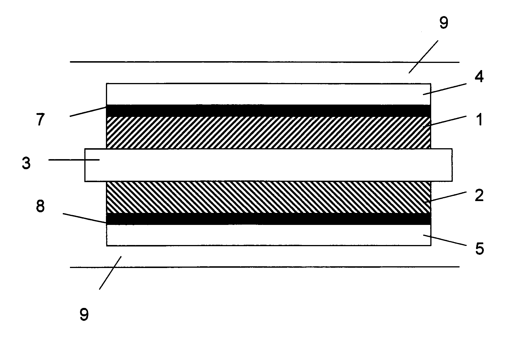
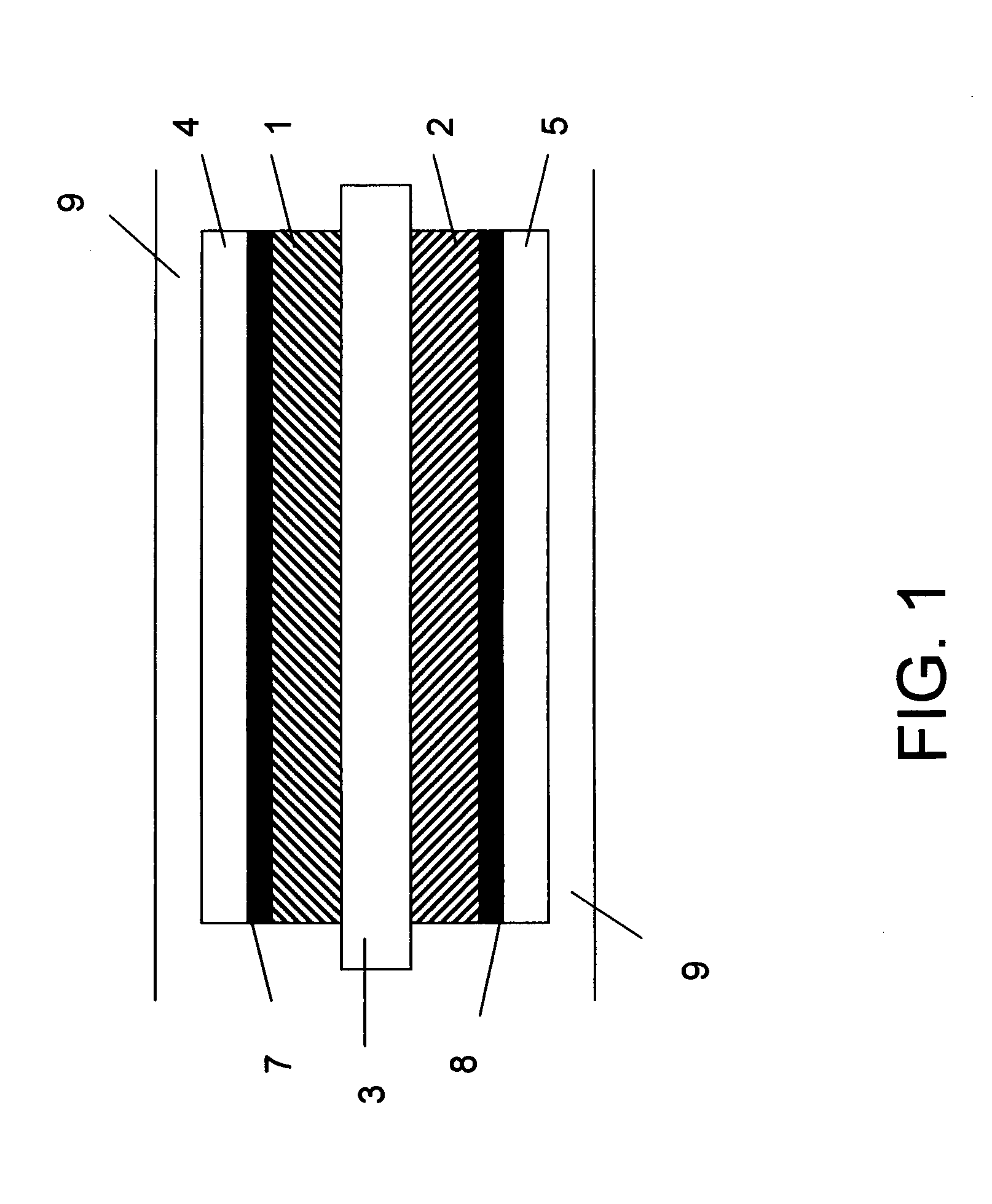
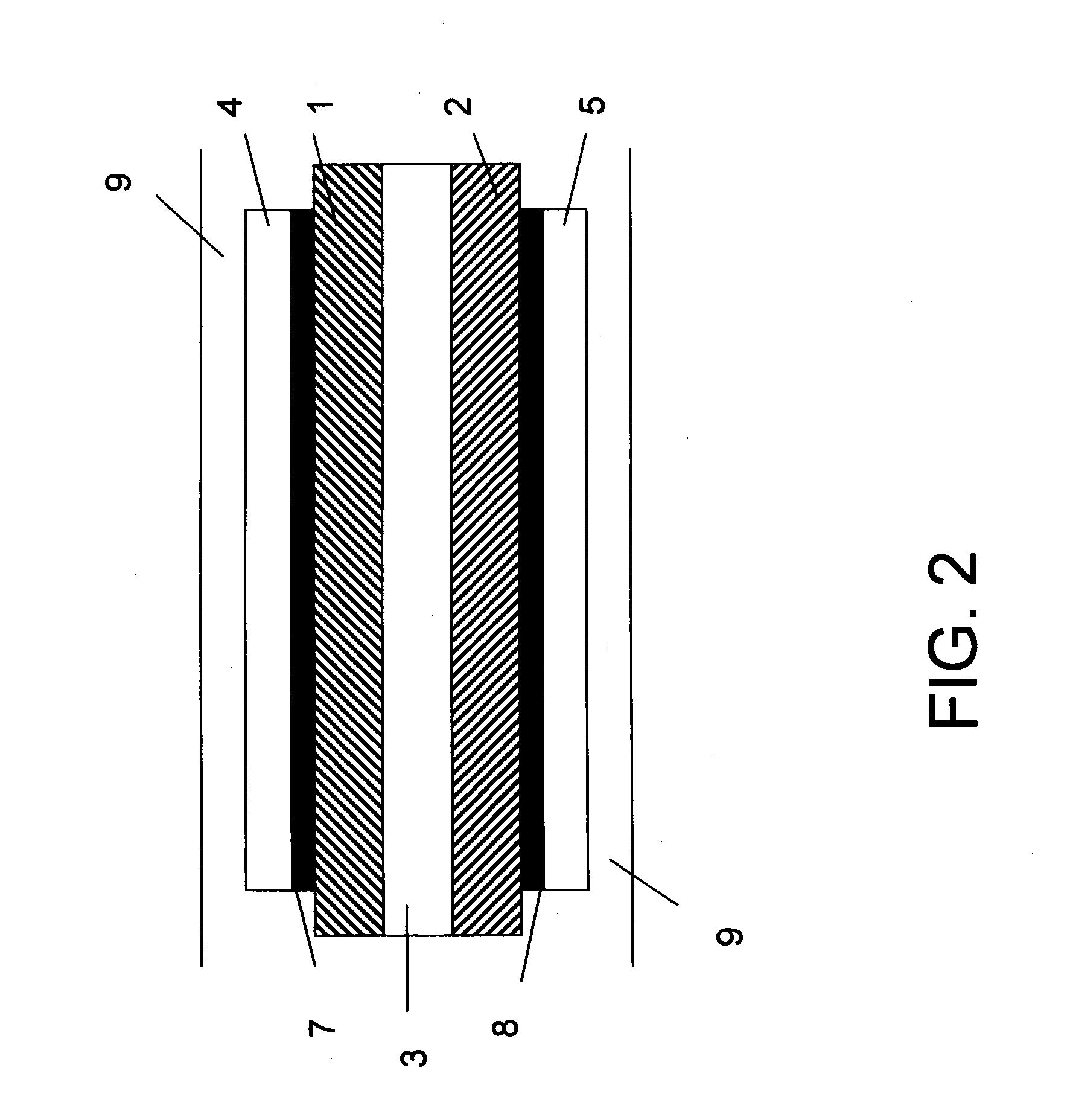
[0052]FIG. 1 shows the different layers of the product in one embodiment of the invention in cross-section. The thin battery of FIG. 1 comprises an anode material layer 7 coated on a paper strip 1 and a cathode material layer 8 coated on another paper strip 2 and a third paper strip 3 there between. The paper strips 1, 2 and 3 form the separator paper layers in the product. The anode and cathode material layers 7, 8 forming the electrodes are covered by collector layers 4, 5 on both sides. The electrodes 7, 8 are in contact to the collectors via the terminals of the collectors 4, 5. The electrical current is fed from the electrodes 7,8 via the collectors 4, 5 to an external circuit. The whole product is further covered in an envelope structure 9.

[0053]The electrodes 7, 8 consisting of the anode and cathode materials 7, 8 are connected to the terminals of the collectors 4, 5 (can not be seen in this cross-section) in order to connect the electrodes 7, 8 to an external circuit. The an...


PUM

PropertyMeasurementUnit
areaaaaaaaaaaa
weightaaaaaaaaaa
conductiveaaaaaaaaaa

Abstract

The thin battery of the invention comprises an anode material, a cathode material, two or more separator paper layers there between, and electrolyte. One of the outer separator paper layers has an anode material applied thereon, another separator paper layer being an outer layer on the opposite side having a cathode material applied thereon. The method of the invention for manufacturing such a thin battery is mainly characterized by the steps of wetting a separator paper with an electrolyte solution, applying an anode material on a first separator paper and applying a cathode material on a second separator paper. The separator papers are then combined by pressing them together so that the anode and cathode materials are outmost, respectively in order to form a layered structure. The combined layers are then cut in desired sizes.

Description

TECHNICAL FIELD[0001]The invention is concerned with a thin battery comprising an anode material and a cathode material, two or more separator paper layers there between, and electrolyte, as well as a method for manufacturing such a battery.BACKGROUND[0002]The basic components of a battery are the electrodes with terminals to connect to an external circuit, a separator to keep the electrodes apart and prevent them from shorting, the electrolyte which carries the charged ions resulting from the chemical reactions taking place at the electrodes and a cover to contain the active chemicals and hold the electrodes in place.[0003]“Wet” cells refer to galvanic cells where the electrolyte is liquid in form and is allowed to flow freely within the cell casing. “Dry” cells are cells that use a solid or powdery electrolyte. These kinds of electrolytes use the ambient moisture in the air to complete the chemical process. Cells with liquid electrolyte can be classified as “dry” if the electrolyt...

Claims


Application Information

Patent Timeline
Patent Type & Authority Applications(United States)
IPC IPC(8): H01M2/16H01M4/82H01M4/04H01M4/50H01M10/0561H01M10/36H01M50/406H01M50/449H01M50/457H01M50/463
CPCH01M2/145Y10T29/49115H01M2/1686H01M2/18H01M4/0407H01M4/0435H01M4/38H01M4/502H01M4/622H01M4/625H01M6/12H01M6/14H01M10/0436H01M10/0561H01M2300/002H01M2/1673Y02E60/10H01M50/46H01M50/463H01M50/449Y02P70/50H01M50/406H01M50/457H01M6/02H01M6/40
Inventor ZHANG, XIA CHANG
Owner ENFUCELL
Why Eureka
Try Eureka