Water jet propulsion watercraft

Inactive Publication Date: 2010-03-25
YAMAHA MOTOR CO LTD
View PDF6 Cites 5 Cited by
  • Summary
  • Abstract
  • Description
  • Claims
  • Application Information

AI Technical Summary

Benefits of technology

[0012]According to the present water jet propulsion watercraft, an extended axial member or other intermediate member does not have to be provided between the crankshaft and the drive shaft. The crankshaft thus does not have to be made small in axial diameter at a connection portion of the crankshaft and such an intermediate member. Consequently, the durability of the crankshaft can be improved.
[0035]The second gear cannot be disposed at the front relative to the flange portion because the flange portion is formed on the crankshaft, and the second gear is thus supported on the crankshaft at the rear relative to the flange portion. The stator unit, which, as mentioned above, makes up the power generator together with the rotor unit that is fixed to the flange portion, can be supported on the main engine body (for example, the crankcase) at the front relative to the flange portion. There is thus no need to secure a space for positioning the stator unit at the rear of the flange portion. The space inside the rotor chamber can thus be utilized effectively to compactly house the stator unit and the second gear. Moreover, workability during attachment of the cover of the rotor chamber can be improved as mentioned above.

Problems solved by technology

There is thus a problem that it is difficult to improve the durability of the crankshaft.

Method used


Image

  • Water jet propulsion watercraft
  • Water jet propulsion watercraft
  • Water jet propulsion watercraft

Examples


Embodiment Construction

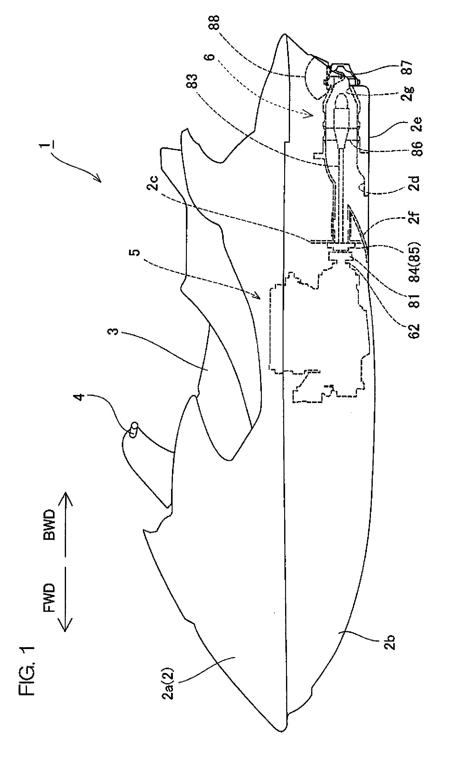
[0045]FIG. 1 is a side view of an overall arrangement of a water jet propulsion watercraft according to a preferred embodiment of the present invention.

[0046]The water jet propulsion watercraft 1 of the preferred embodiment includes a hull 2, a seat 3, a steering apparatus 4, an engine 5, and a jet propulsion unit 6. The hull 2 is made up of a deck 2a and a hull body 2b. The seat 3 is disposed on an upper portion of the hull 2. The steering apparatus 4 arranged for an operator to steer the hull 2 is disposed in front of the seat 3. The engine 5 is disposed in an engine room formed in an interior of the hull body 2b. The jet propulsion unit 6 is disposed at the rear of the engine 5 inside the hull body 2b.

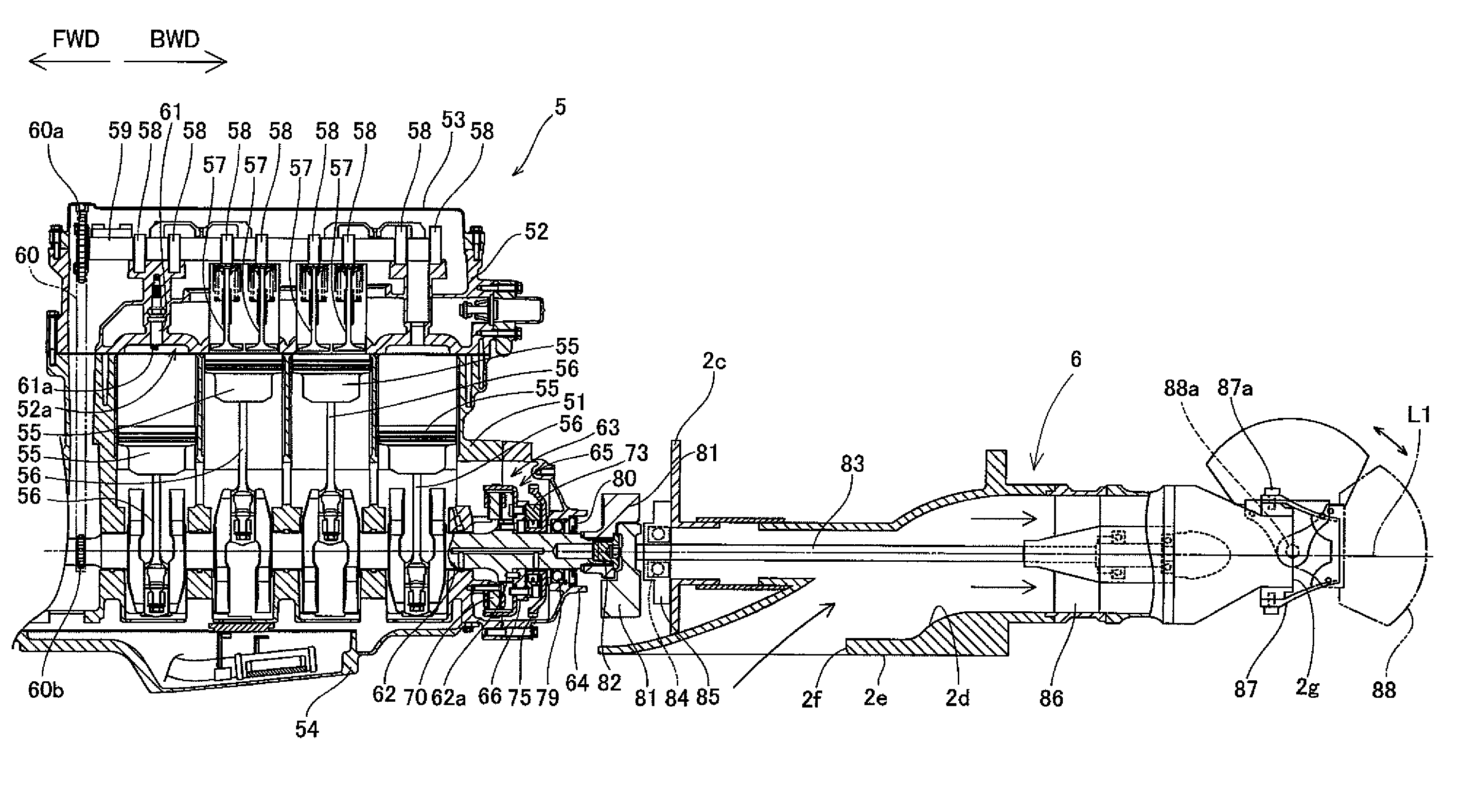
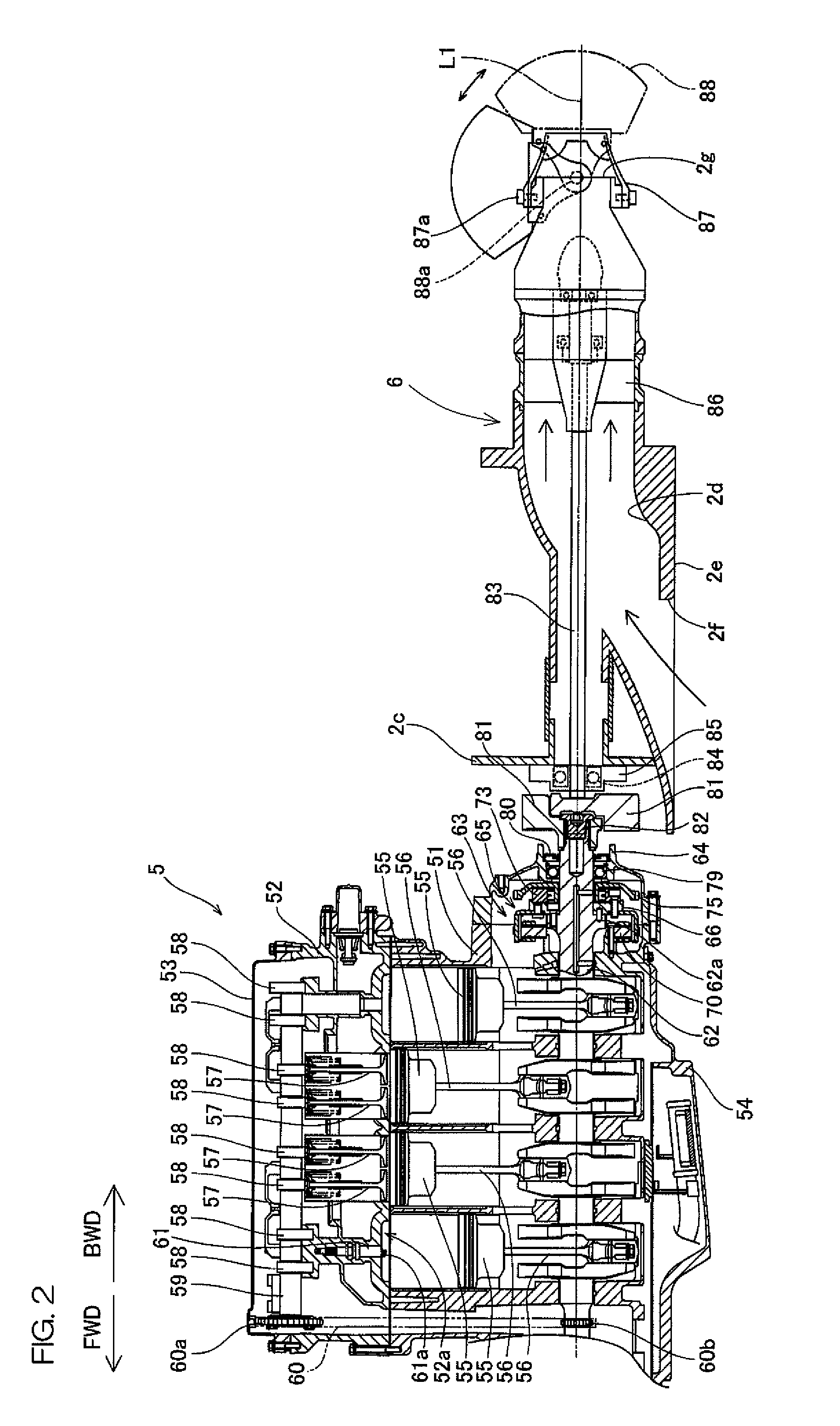
[0047]FIG. 2 is an enlarged sectional view of the engine 5 and the jet propulsion unit 6. The jet propulsion unit 6 includes a drive shaft 83, an impeller 86, a deflector 87, and a reverse bucket 88. A crankshaft 62 protrudes from a rear portion of the engine 5, and a coupling memb...


PUM


Abstract

A water jet propulsion watercraft includes a main engine body, a rotor chamber disposed at a rear portion of the main engine body, a crankshaft disposed so as to extend penetratingly through the rotor chamber such that a rear end portion thereof protrudes to an outer side of the rotor chamber, a rotor unit coupled to the crankshaft inside the rotor chamber, a drive shaft connected to the rear end portion of the crankshaft and rotated together with the crankshaft, and a jet propulsion unit, having an impeller that is coupled to the drive shaft, and arranged to suck in and jet out water. The crankshaft includes a flange portion that is integral with the crankshaft inside the rotor chamber. The rotor unit is fixed to the flange portion.

Description

BACKGROUND OF THE INVENTION[0001]1. Field of the Invention[0002]The present invention relates to a water jet propulsion watercraft including a jet unit (jet propulsion device) having an engine (internal combustion engine) as a drive source.[0003]2. Description of Related Art[0004]An example of a water jet propulsion watercraft is disclosed in U.S. Patent Application Publication No. 2004 / 0194682 A1. This water jet propulsion watercraft includes a hull, a water jet pump, and an engine. The engine applies a driving force to the water jet pump. The water jet pump includes a propeller shaft rotated by the driving force of the engine, and an impeller coupled to the propeller shaft. By rotation of the propeller shaft, water is sucked in from a hull bottom and the water is jetted rearward by the impeller. A propulsive force is thereby applied to the hull.[0005]The engine has a crankcase at a lower side. A crankshaft housed in the crankcase is extended to a rear of the crankcase, and an exte...

Claims


Application Information

Patent Timeline
IPC IPC(8): B63H11/02
CPCB63H2011/081B63H11/08
Inventor NAKAMURA, MITSUYOSHI
Owner YAMAHA MOTOR CO LTD
Why Eureka
Try Eureka