Robotic vehicle for performing rail-related actions

a robot vehicle and rail technology, applied in the field of robot systems, can solve the problems of long operation period, high stress on railroad wheels, wear on wheels,

Active Publication Date: 2010-03-25
INT ELECTRONICS MACHINES
View PDF39 Cites 108 Cited by
  • Summary
  • Abstract
  • Description
  • Claims
  • Application Information

AI Technical Summary

Benefits of technology

[0010]A first aspect of the invention provides a vehicle configured for autonomous operation, the vehicle comprising: a first imaging device configured to acquire location image data; a transport component configured to enable the vehicle to move independently; a processing component configured to process the location image data acquired by the first imaging device and operate the transport component to move the vehicle using the location image data; a set of action components, the set of action components including at least one component configured to be temporarily secured with respect to a target object external to the vehicle; means for moving the at least one component to temporarily secure the at least one component with respect to the target object; and means for enabling the set of action components to move freely with the target object after the at least one component is temporarily secured.

Problems solved by technology

During use, railroad wheels are subjected to high, long-term stresses.
Despite being made of high-quality steel, the stresses cause the wheels to become worn over a long period of operation.
Without maintenance, a wheel can become too thin or otherwise no longer of the correct geometry.
Further, the wheels may develop other defects, such as, for example, a “slid flat” or “flat spot”, which is caused by locking the wheels with the brakes in an attempt to stop.
As a result, any difference between the shape and / or size of the wheels on either side of a car / locomotive can cause a tendency to turn, leading to an increased possibility of derailment.
Often, due to time constraints, only a few cars are actually inspected and / or the inspection is only cursory (e.g., visual inspection).
Additionally, this approach does not provide a solution capable of performing other operations that may be necessary to completely decouple / couple rail vehicles (e.g., disassembly / assembly of brake hose) and / or may be desired (e.g., security, cleaning, inspection, and / or the like).

Method used


Image

  • Robotic vehicle for performing rail-related actions
  • Robotic vehicle for performing rail-related actions
  • Robotic vehicle for performing rail-related actions

Examples


Embodiment Construction

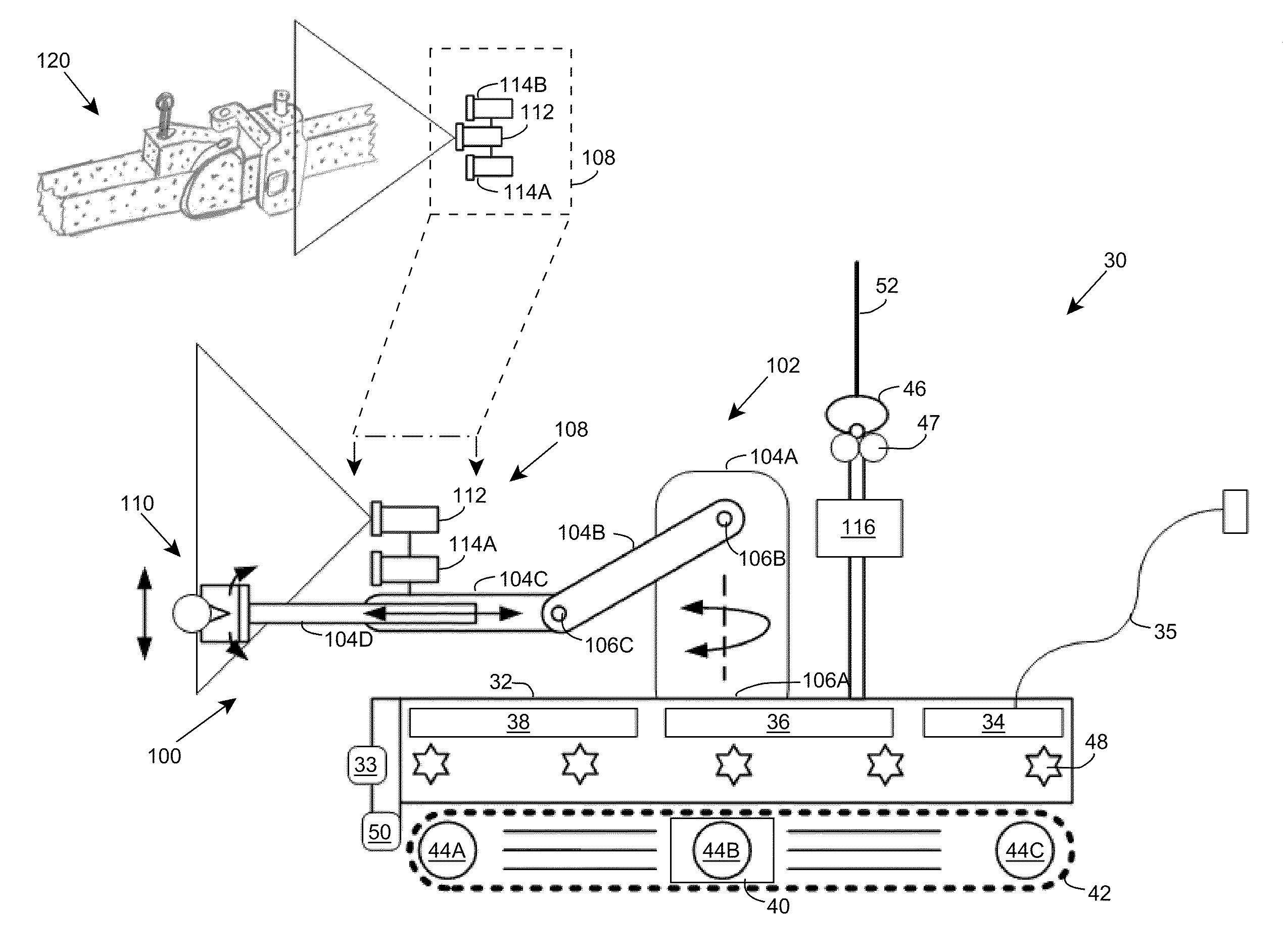
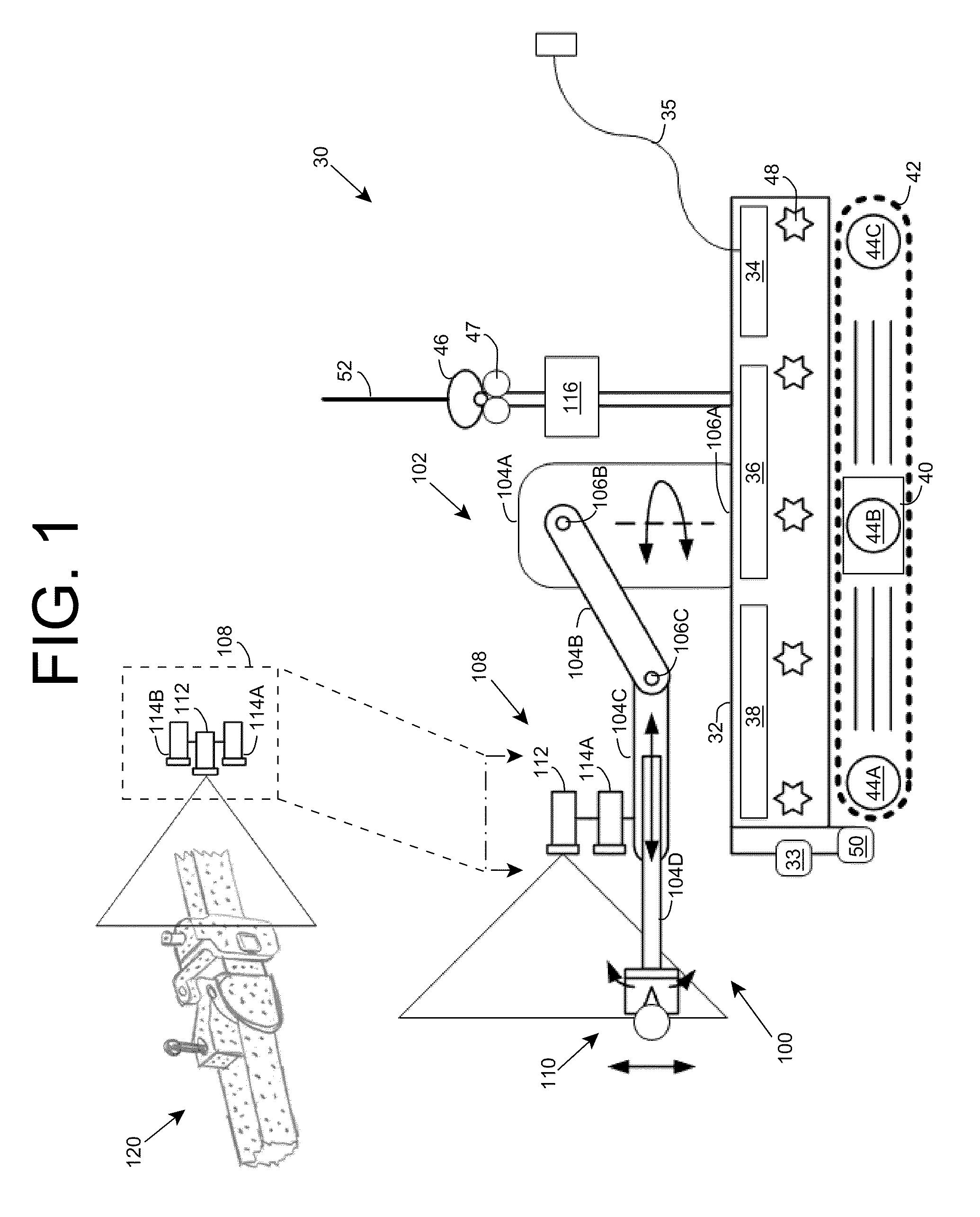
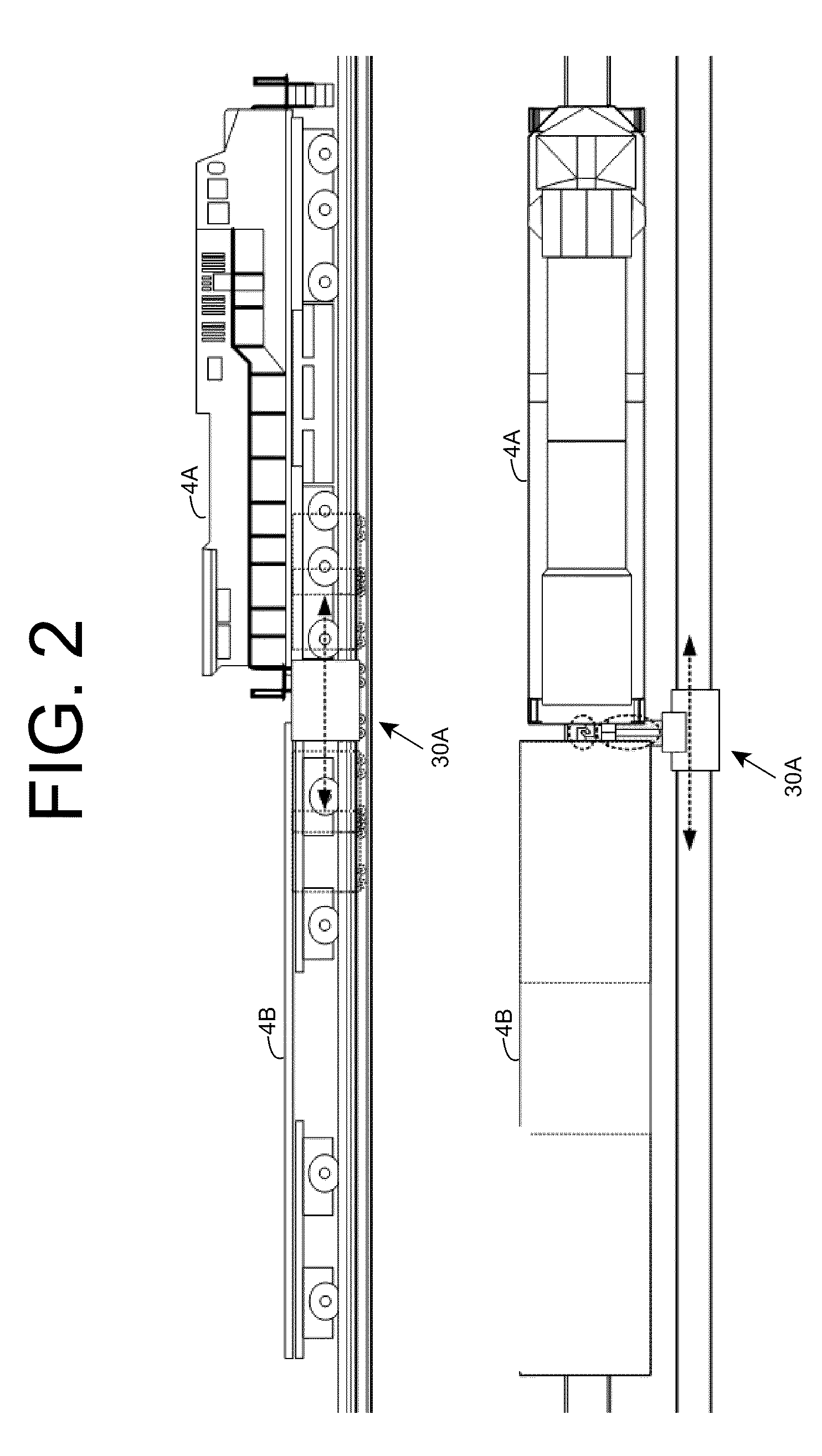
[0029]As indicated above, aspects of the invention provide a robotic vehicle configured for autonomous or semi-autonomous operation in a rail environment. The vehicle can process image data to move about the rail environment and perform one or more actions in the rail environment. The actions can include one or more actions related to decoupling and / or attaching rail vehicles, and can be implemented by performing three-dimensional image processing. The vehicle can be configured to move with any movement of a rail vehicle on which one or more actions are being performed. In an alternative embodiment, the various components configured to perform the action are implemented at a stationary location with respect to a rail line. As used herein, unless otherwise noted, the term “set” means one or more (i.e., at least one) and the phrase “any solution” means any now known or later developed solution.

[0030]An embodiment provides a robotic vehicle capable of fully autonomous and / or semi-auton...


PUM


Abstract

A robotic vehicle configured for autonomous or semi-autonomous operation in a rail environment is provided. The vehicle can process image data to move about the rail environment and perform one or more actions in the rail environment. The actions can include one or more actions related to decoupling and/or attaching rail vehicles, and can be implemented by performing three-dimensional image processing. The vehicle can be configured to move with any movement of a rail vehicle on which one or more actions are being performed. In an alternative embodiment, the various components configured to perform the action are implemented at a stationary location with respect to a rail line.

Description

REFERENCE TO PRIOR APPLICATIONS[0001]The current application claims the benefit of co-pending U.S. Provisional Application No. 61 / 136,624, titled “Robotic vehicle to perform railway maintenance”, which was filed on 19 Sep. 2008, and which is hereby incorporated by reference. Aspects of the disclosure are related to U.S. Utility Patent Application No. 12 / 043,357, titled “Rail vehicle Identification and processing”, which was filed on 6 Mar. 2008, and U.S. Utility Patent Application No. 12 / 171,438, titled “Rail vehicle identification and processing”, which was filed on 11 Jul. 2008, each of which is hereby incorporated by reference.TECHNICAL FIELD[0002]The disclosure relates generally to a robotic system, and more particularly to processing objects, such as rail vehicles, using a robotic system.BACKGROUND ART[0003]During use, railroad wheels are subjected to high, long-term stresses. Despite being made of high-quality steel, the stresses cause the wheels to become worn over a long per...

Claims


Application Information

Patent Timeline
Patent Type & Authority Applications(United States)
IPC IPC(8): G06F17/00G05D1/00
CPCB61C17/12G05D1/0229B61G7/04B25J5/005B25J5/007G05D1/0231G05D1/0274G05D1/0276
Inventor MIAN, ZAHID F.
Owner INT ELECTRONICS MACHINES
Why Eureka
Try Eureka