Heat pump drying machine

a drying machine and heat pump technology, applied in drying machines, heat pumps, lighting and heating equipment, etc., can solve the problems of reducing drying efficiency, affecting drying efficiency, and affecting drying efficiency, so as to achieve short drying time, reduce compressor input energy, and facilitate operation control

Inactive Publication Date: 2010-04-01
SANYO ELECTRIC CO LTD
View PDF10 Cites 62 Cited by
  • Summary
  • Abstract
  • Description
  • Claims
  • Application Information

AI Technical Summary

Benefits of technology

[0021]Yet further, the operation control unit may be configured to set the operation frequency, which is enough to remove the frost generated in the evaporator, to the predetermined operation frequency in the first dry operation mode. According to the construction, the heat pump drying machine is merely required to switch the second dry operation mode to the first dry operation mode. Therefore, the operation control can be easily executed.
[0022]According to the present invention, the operation frequency of the compressor is controlled in the condition that the compression ratio is equal to or greater than 3.0. Accordingly, temperature of the air to be supplied to the accommodation room is increased in accordance with the increase of temperature of the refrigerant discharged from the compressor. Therefore, the first dry operation with a short drying time can be executed. Furthermore, the operation frequency of the compressor is controlled in the condition that the...

Problems solved by technology

During this period, such a condition that pressure of the compressor cannot be easily increased occurs.
In this case, condensed water generated in the evaporator is frozen there, and the frozen condensed water may block the air blowing path.
Consequently, there occurs such a drawback that the air cannot be circulated in both ...

Method used


Image

  • Heat pump drying machine
  • Heat pump drying machine
  • Heat pump drying machine

Examples


Embodiment Construction

[0030]With reference to the accompanying figures, an embodiment of the present invention will be hereinafter described in detail.

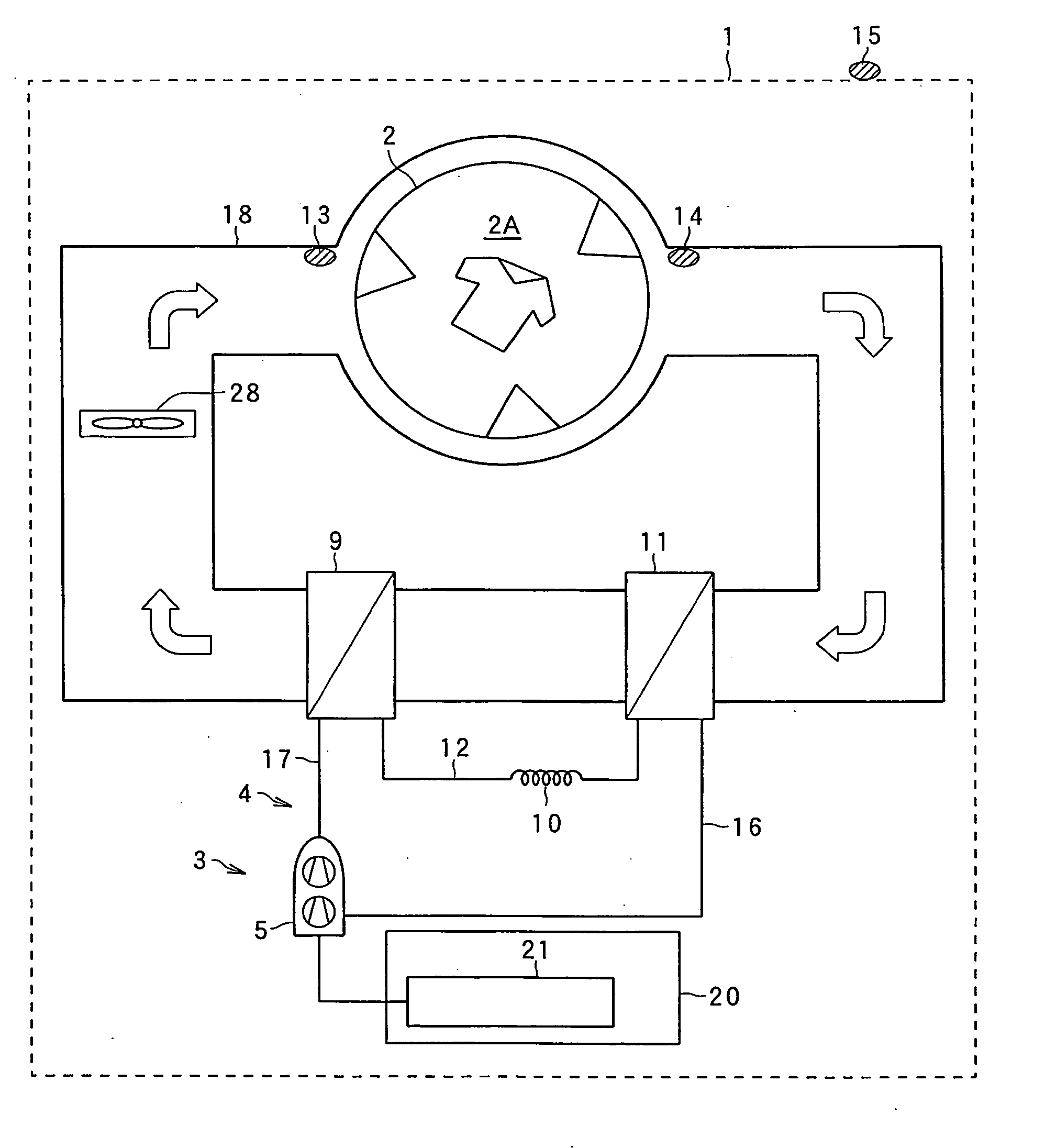
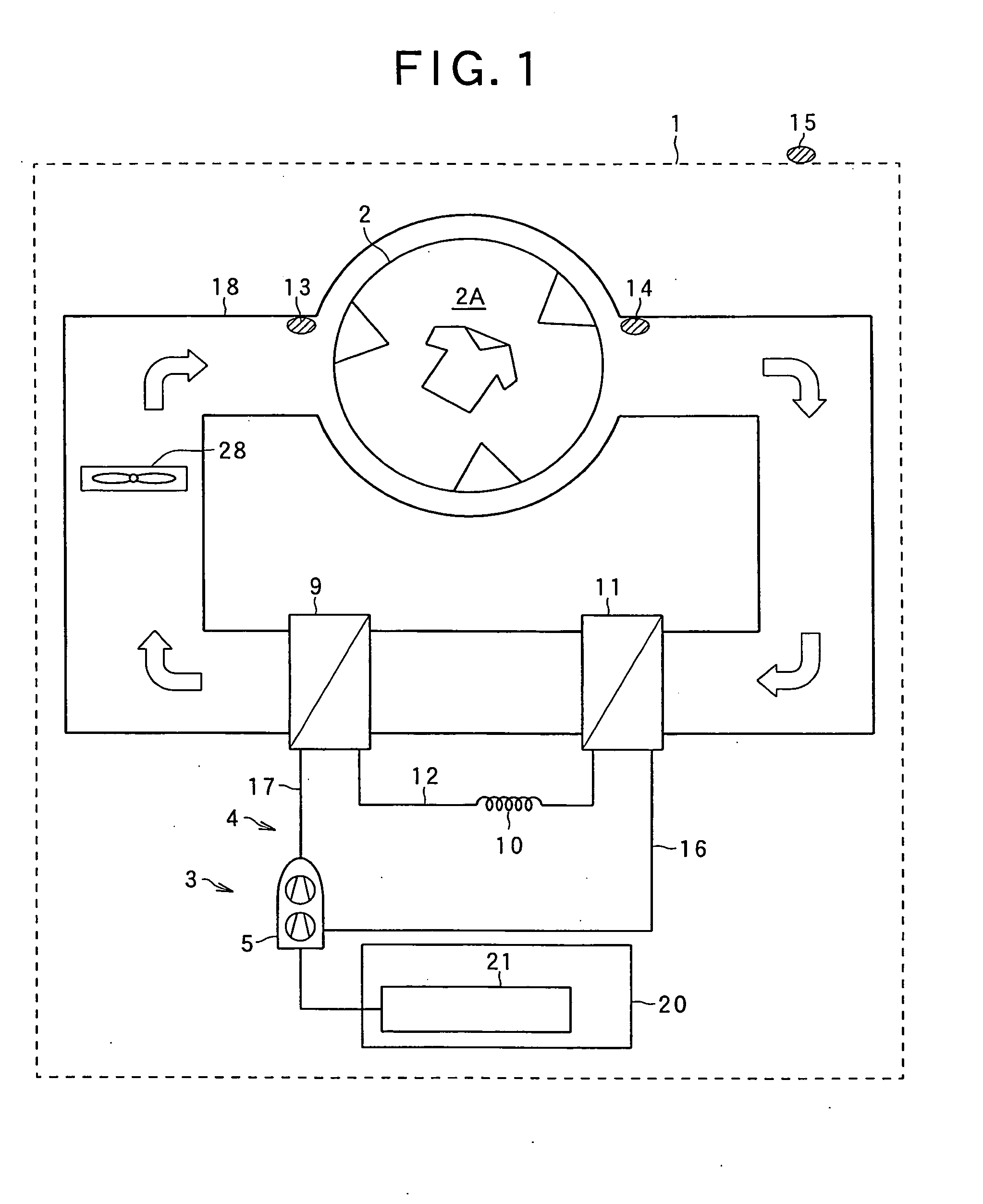
[0031]FIG. 1 illustrates an embodiment of a drying machine to which the present invention is applied.

[0032]In FIG. 1, reference numeral 1 represents a heat pump drying machine, and reference numeral 2 represents a cylindrical rotary drum having a large number of apertures formed in the circumferential wall thereof. Clothing (drying target) is dried in an accommodation room 2A at the inside of the drum 2. The drum 2 is rotated by a drum motor (not illustrated in the figure).

[0033]Reference numeral 3 represents a heat pump device having a refrigeration circuit 4. The refrigeration circuit 4 includes a compressor 5, a gas cooler 9 functioning as a radiator, a capillary tube (expansion device) 10, an evaporator 11 and the like. Carbon dioxide (CO2) refrigerant is sealingly filled in the refrigeration circuit 4.

[0034]The compressor 5 is an inner intermediate-pr...


PUM


Abstract

An heat pump drying machine has a normal dry mode (e.g., compression ratio is equal to or greater than 3) for operating a compressor at a predetermined dry operation frequency and an energy saving dry mode (e.g., compression ratio is equal to or greater than 2.3 and is less than 3) for operating the compressor at an energy saving operation frequency that is lower than the dry operation frequency. A control device is provided to control an operation frequency of the compressor 5 so that the two dry operation modes are switched to each other. The control device can execute the control for increasing the operation frequency of the compressor to the dry operation frequency during the operation of the energy saving dry mode.

Description

INCORPORATION BY REFERENCE[0001]The present application claims priority under 35 U.S.C. §119 to Japanese Patent Application No. 2008-253357 filed on Sep. 30, 2008 and Japanese Patent Application No. 2008-253356 filed on Sep. 30, 2008. The content of the applications is incorporated herein by reference in its entirety.BACKGROUND OF THE INVENTION[0002]1. Field of the Invention[0003]The present invention relates to a heat pump drying machine which is provided with an accommodation room for accommodating a drying target and is configured to execute a dry operation for the drying target in the accommodation room.[0004]2. Related Art[0005]The heat pump drying machine is generally known to have the following configuration. The heat pump drying machine is provided with a rotary drum and a heat pump. The rotary drum accommodates a drying target. The heat pump is provided with a refrigeration circuit comprising a compressor, a radiator, an expansion device, an evaporator and the like. The hea...

Claims


Application Information

Patent Timeline
IPC IPC(8): F25B13/00
CPCD06F58/206F25B2309/061F25B49/022F25B30/02
Inventor MASUDA, TETSUYAKURIBARA, HIROYUKIIMAI, SATOSHIISHIHARA, TOSHIKAZUSATO, KEIJIYAMASAKI, HARUHISAFUKUDA, EIJINOGUCHI, YOSHIAKI
Owner SANYO ELECTRIC CO LTD
Why Eureka
Try Eureka