Cleaning device and cleaning method

a cleaning device and cleaning method technology, applied in the direction of cleaning process and equipment, cleaning chemistry apparatus and processes, etc., can solve the problems of inability to clean, inability to clean, and inability to clean during the cleaning process, so as to increase the cleaning time

Inactive Publication Date: 2010-04-01
PANASONIC CORP
View PDF4 Cites 1 Cited by
  • Summary
  • Abstract
  • Description
  • Claims
  • Application Information

AI Technical Summary

Benefits of technology

[0007]In the conventional technology, however, a cleaning time during which the chemical solution is removed from the semiconductor substrate and the contents of the rinsing tank are completely replaced with ultrapure water is inevitably increased in the case where a considerable amount of the chemical solution is brought into the rinse treatment after the chemical solution treatment. Usually, the surface of the semiconductor substrate is not etched in the rinsing tank, unlike in the chemical solution treatment. However, when a large amou

Problems solved by technology

In the conventional technology, however, a cleaning time during which the chemical solution is removed from the semiconductor substrate and the contents of the rinsing tank are completely replaced with ultrapure water is inevitably increased in the case where a considerable amount of the chemical solution is brought into the rinse treatment after the chemical solution treatment.
However, when a large amount of chemical solution is attached to a lifter which retains the semiconductor substrate, a considerable amount of the chemical solution is brought into the rinsing tank.
In the case of a semiconductor substrate provided with a thin film formed on a surface thereof, in

Method used


Image

  • Cleaning device and cleaning method
  • Cleaning device and cleaning method
  • Cleaning device and cleaning method

Examples


embodiment 1

Preferred Embodiment 1

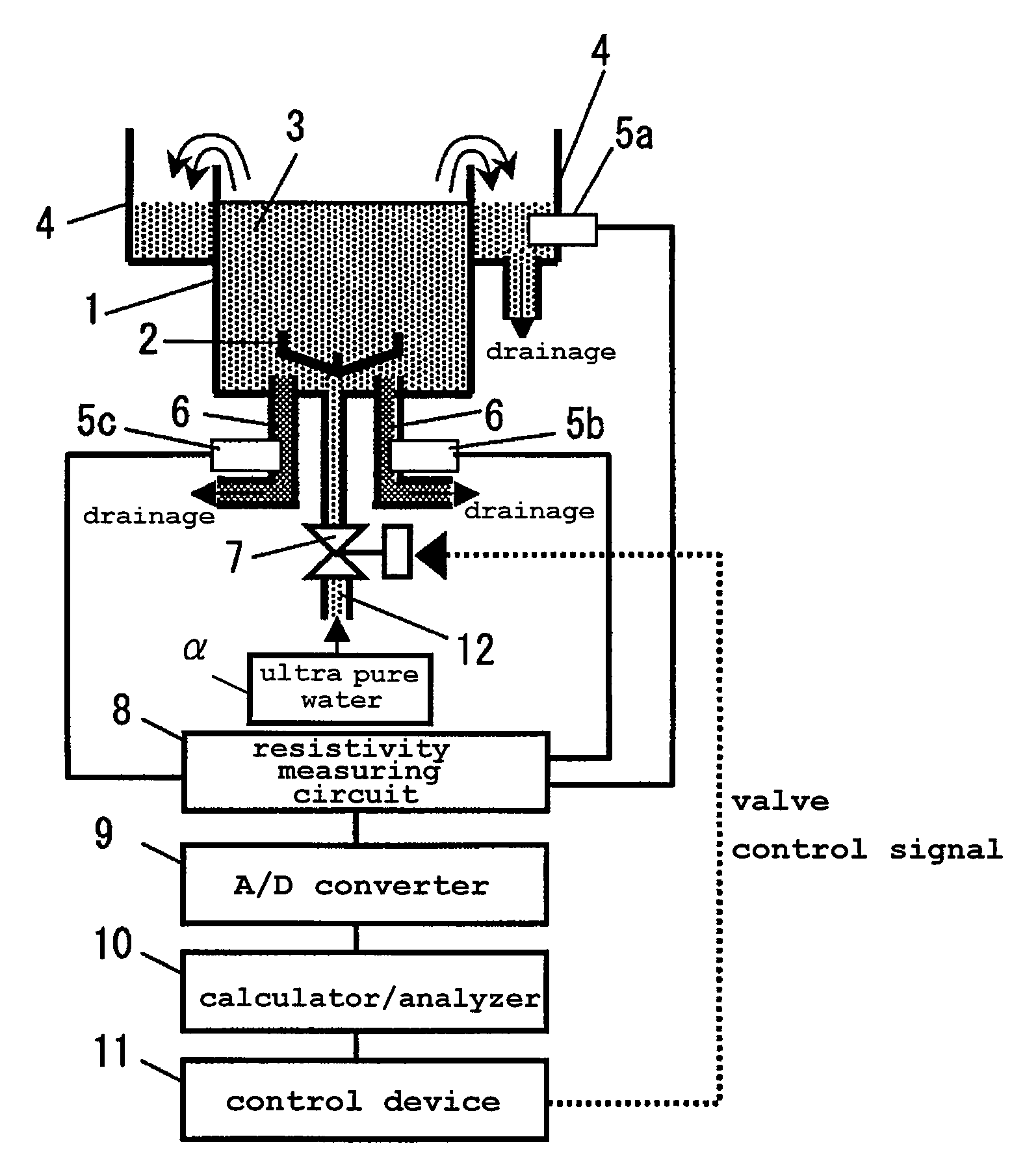
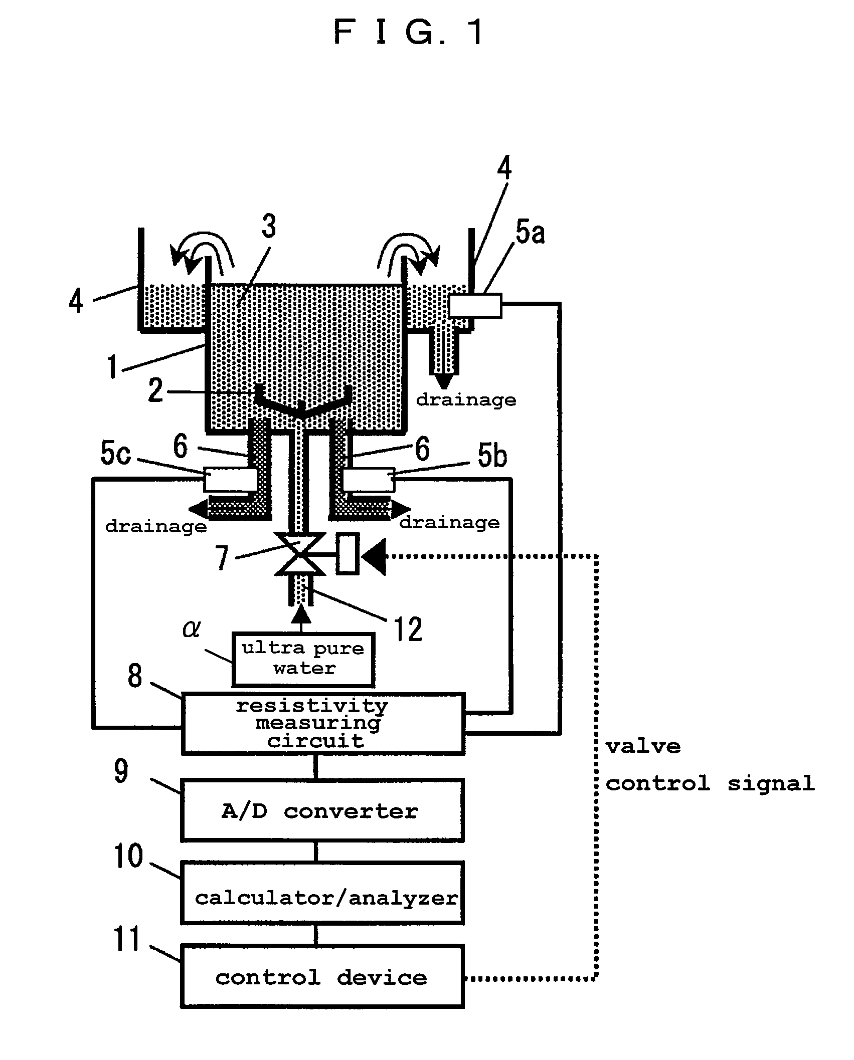
[0043]FIG. 1 is a schematic illustration of a constitution of a soak cleaning device according to a preferred embodiment of the present invention. A rinsing tank 1 is a cleaning tank in which one or a plurality of semiconductor substrates cleaned with a chemical solution are contained while being retained by a lifter 2, and the lifter 2 alone is rinsed with pure water after the semiconductor substrate is cleaned. At a bottom section of the rinsing tank 1, a pipe 12 for supplying ultrapure water 3 used for rinsing the semiconductor substrate and the lifter 2 from a pure water supply source a to the rinsing tank 1 is set, and a pure water supply valve 7 is provided in the pipe 12. When the pure water supply valve 7 is opened or closed, the supply of the ultrapure water 3 starts or stops. When the ultrapure water 3 in the rinsing tank 1 (including the chemical solution attached to the semiconductor substrate or the lifter 2) overflows the rinsing tank 1, the rinsi...


PUM

PropertyMeasurementUnit
Flow rateaaaaaaaaaa
Threshold limitaaaaaaaaaa
Electrical resistivityaaaaaaaaaa

Abstract

An initial resistivity value of pure water is measured. A lifter is cleaned in a state where the pure water is continuously supplied to the rinsing tank to replenish the rising tank while the pure water is being drained from the rinsing tank. A resistivity value of the pure water in process of cleaning the lifter is measured at predetermined time intervals. A difference value between each of the resistivity values and the initial resistivity value is calculated, and the calculated difference values are integrated. An amount of residual chemical solution of the lifter in process of being cleaned is calculated based on an integration result thus obtained. A period of cleaning time necessary for the lifter to become clean in a state where a flow rate of the drained/replenishing pure water per unit time is maintained is calculated based on the amount of residual chemical solution. The lifter is continuously cleaned in the state where the flow rate of the drained/replenishing pure water per unit time is maintained until the period of cleaning time elapses.

Description

BACKGROUND OF THE INVENTION[0001]1. Field of the Invention[0002]The present invention relates to a cleaning device and a cleaning method used in a semiconductor substrate treating process and more particularly to a cleaning device and a cleaning method for performing a final rinsing step of a wet treatment.[0003]2. Description of the Related Art[0004]In this specification of the present patent application, the entire recitations of the Japanese Patent Application No. 2008-253188 filed on Sep. 30, 2008, including its specification, drawings and Scope of Claims, are hereby incorporated by reference.[0005]As is well known in the art, a ultrapure water rinsing method (an overflow rinsing method) is conventionally adopted in a semiconductor substrate cleaning method. The overflow rinsing method is aimed at thoroughly cleaning a semiconductor substrate by removing chemical solution attached thereto after a chemical solution treatment using a solution in which hydrochloric acid and hydroge...

Claims


Application Information

Patent Timeline
IPC IPC(8): B08B3/00
CPCH01L21/67253H01L21/67057B08B3/048
Inventor KITABATA, MASAKIIMAI, SHIN-ICHI
Owner PANASONIC CORP
Why Eureka
Try Eureka