Simplified beam splitter for ir gas sensor

Active Publication Date: 2010-04-01
GENERAL ELECTRIC CO
View PDF13 Cites 16 Cited by
  • Summary
  • Abstract
  • Description
  • Claims
  • Application Information

AI Technical Summary

Benefits of technology

[0013]Gas analyzers like the ones described can be used for monitoring respiratory gases from a patient. In most cases at least carbon dioxide is measured. Therefore it is important to be able to produce such sensors cost effectively. This is especially true for mainstream sensors, which measure the respiratory gas directly at the ventilator tube. These sensors must also be small and

Problems solved by technology

Further, a thin semi-reflective membrane, a pellicle, is a possible beam splitter solution but it may not be robust enough in many cases and it can be sensitive to temperature fluctuations, and its reliable fastening is also a problem.
Accordingly, both independent single path analyzer channels have measuring detectors positioned to receive the transmitting portion of the radiation beam and reference detectors positioned to receive the reflected portions of the radiation beam, while in the first analyzer channel there is a reference filter between the beam splitter and

Method used


Image

  • Simplified beam splitter for ir gas sensor
  • Simplified beam splitter for ir gas sensor
  • Simplified beam splitter for ir gas sensor

Examples


Embodiment Construction

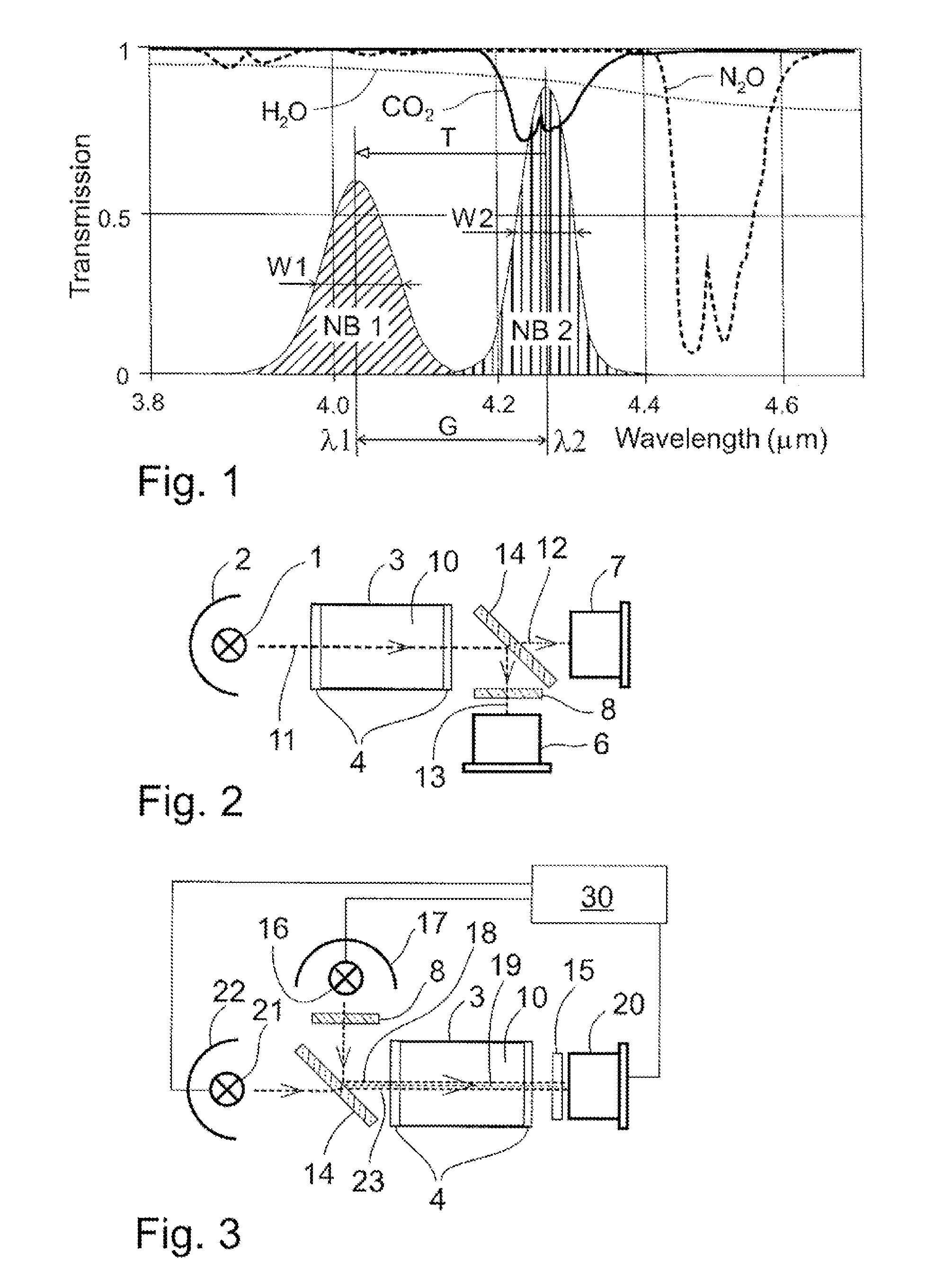
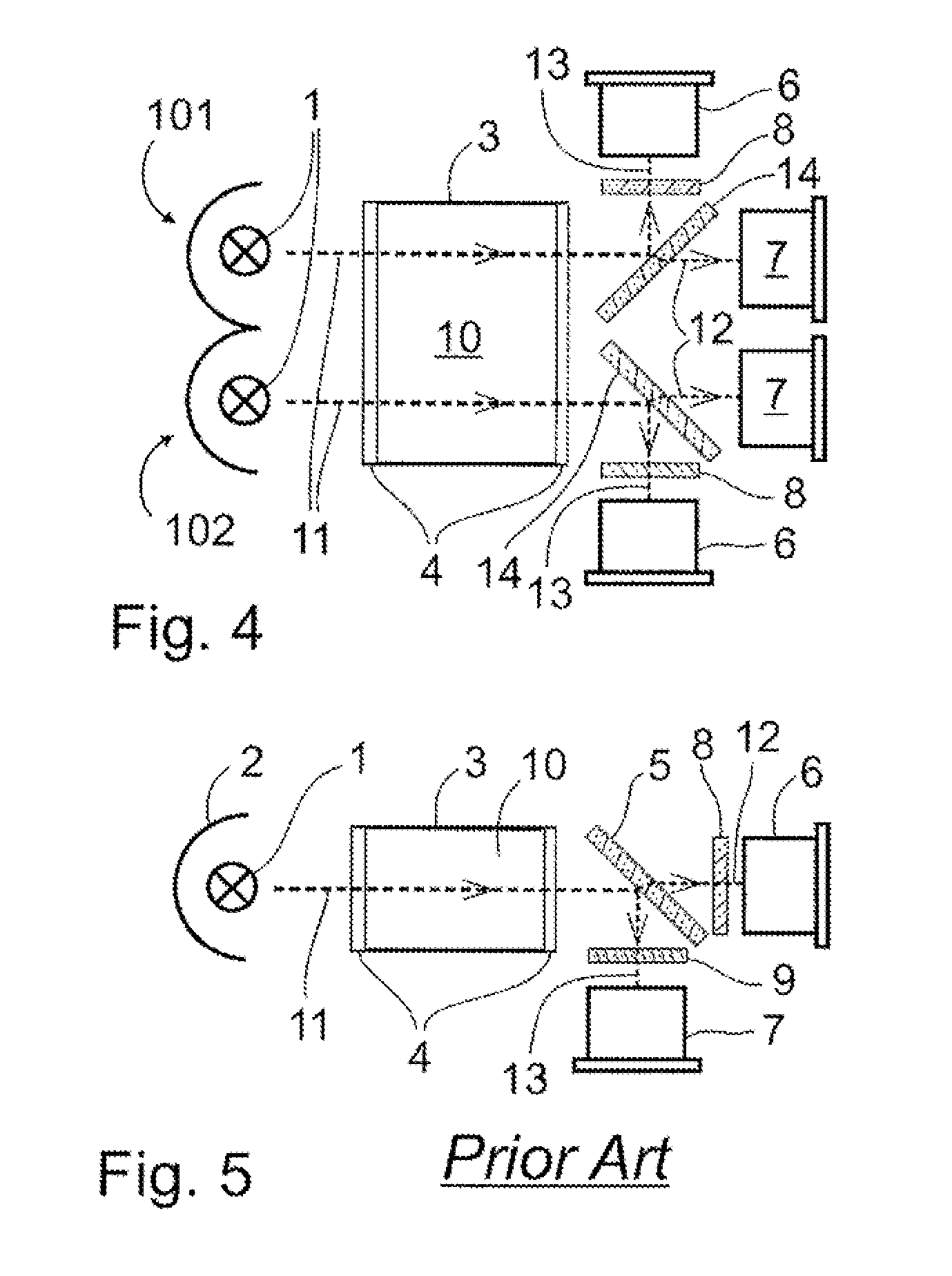
[0021]One of the preferred embodiments of the invention is a non-dispersive single beam detection assembly in an infrared gas analyzer comprising, depending on the type of construction, at least one radiation source 1 or 16, 21, which provide(s) infrared radiation as a beam 11, 19 into and through a measuring chamber 3. The measuring chamber contains the gas mixture 10 with a gas component to be measured, whereupon the concentration of the gas component to be measured may be from zero to some maximum value. The assembly also comprises a physical beam splitter 14 either for dividing the radiation beam 11 into a reflected beam portion 13 and a transmitted beam portion 12, or for combining a reflected beam portion 18 and a transmitted beam portion 23 into the radiation beam 19. In the former alternative, i.e. with dividing beam splitter as shown in FIG. 2, the assembly has one radiation source 1, and the latter alternative, i.e. with combining beam splitter as shown in FIG. 3, the asse...


PUM


Abstract

A non-dispersive single beam detection assembly in an infrared gas analyzer. The detection assembly comprises radiation source(s) providing infrared radiation, a measuring chamber, and a physical beam splitter for dividing said radiation beam into a reflected beam portion and a transmitted beam portion, or for combining a reflected beam portion and a transmitted beam portion into said radiation beam. A measuring detector receives one beam portions, and a reference detector receives another beam portion. Alternatively a measuring/reference detector receives both beam portions. Said transmitted beam portion has a first spectral intensity peak at shorter wavelengths with a first peak wavelength, and said reflected beam portion has a second spectral intensity peak at longer wavelengths with a second peak wavelength. There is a wavelength gap between said second peak wavelength and said first peak wavelength, which gap corresponds a wavelength shift of an optical interference filter with said second peak wavelength as tilted from its perpendicular position to an angled position. Said wavelength gap is at maximum 10% of the second peak wavelength, and at minimum 0.5% of the second peak wavelength.

Description

CROSS-REFERENCE TO RELATED APPLICATIONS[0001]This application claims priority under 35 U.S.C. §119(a)-(d) or (f) to prior-filed, co-pending European patent application number EP08165473.3, filed on Sep. 30, 2008, which is hereby incorporated by reference in its entirety.STATEMENT REGARDING FEDERALLY SPONSORED RESEARCH OR DEVELOPMENT[0002]Not ApplicableNAMES OF PARTIES TO A JOINT RESEARCH AGREEMENT[0003]Not ApplicableREFERENCE TO A SEQUENCE LISTING, A TABLE, OR COMPUTER PROGRAM LISTING APPENDIX SUBMITTED ON COMPACT DISC[0004]Not ApplicableBACKGROUND OF THE INVENTION[0005]1. Field of the Invention[0006]The subject matter disclosed herein relates generally to a gas measuring device based on infrared absorption and, specifically, to a simplified filter and beam splitter arrangement used to divide a source radiation into a measuring and a reference part or to combine the radiation from a measuring and a reference source into one radiation path. The measuring device is typically a single ...

Claims


Application Information

Patent Timeline
IPC IPC(8): G01J5/02
CPCG01J3/427G01N2021/3177G01N21/3504
Inventor HAVERI, HEIKKIWECKSTROM, KURT PETER
Owner GENERAL ELECTRIC CO
Why Eureka
Try Eureka