
Light emitting device and method of fabricating the same

a technology of light emitting device and manufacturing method, which is applied in the direction of semiconductor/solid-state device manufacturing, semiconductor/conductor device manufacturing, electrical apparatus, etc., can solve the problems of reducing light emitting efficiency, large amount of light loss, and inability to form thick gan layer of typ

Active Publication Date: 2010-04-01
SEOUL VIOSYS CO LTD
View PDF11 Cites 230 Cited by
  • Summary
  • Abstract
  • Description
  • Claims
  • Application Information

AI Technical Summary

Benefits of technology

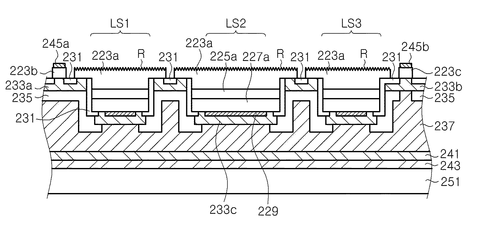
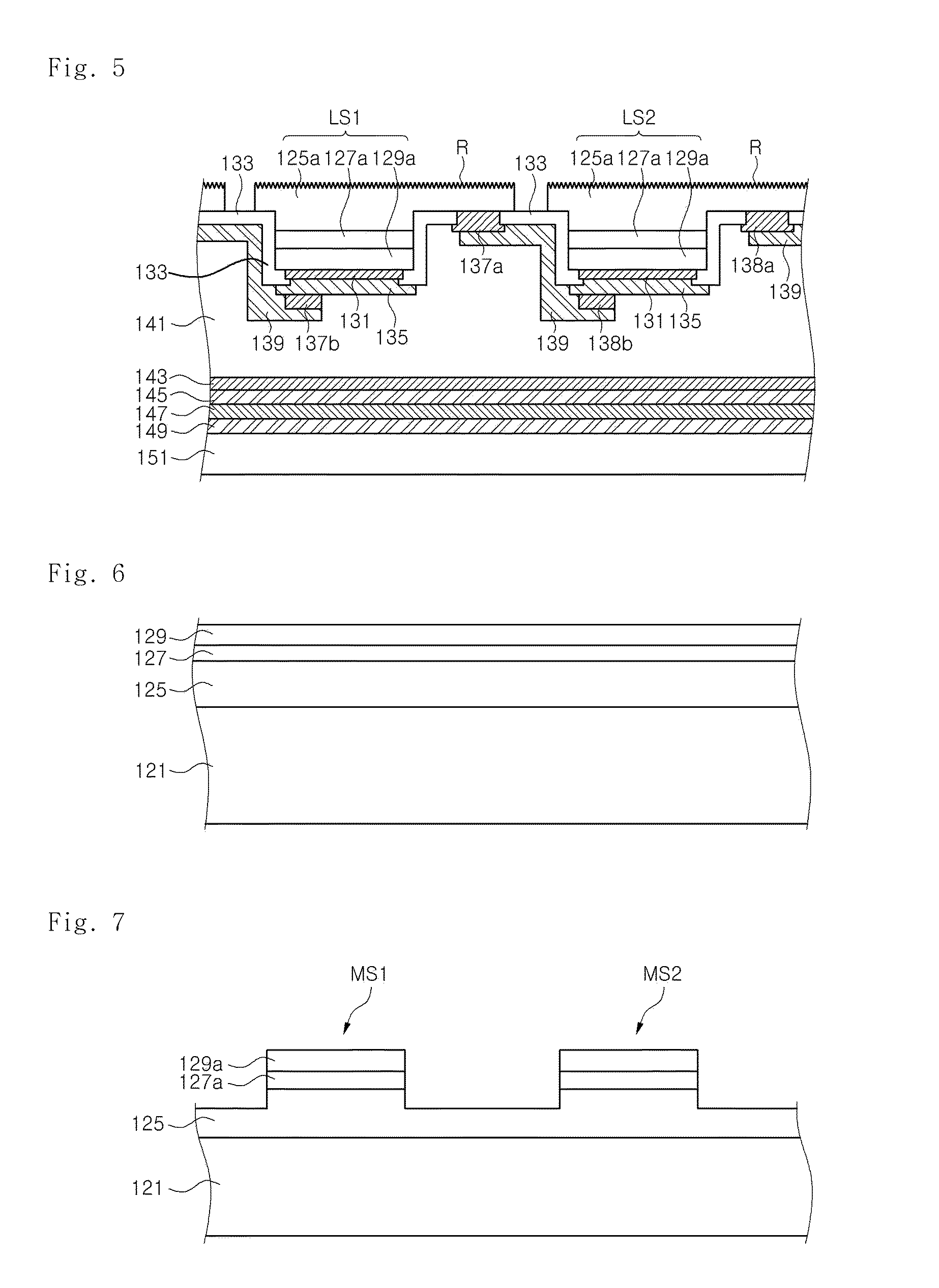
[0022]Exemplary embodiments of the present invention provide a light emitting device, in which a short circuit in a light emitting cell due to metallic etch byproducts can be prevented, and a method of fabricating the light emitting device.
[0023]Exemplary embodiments of the present invention also provide a light emitting device, in which loss of light traveling toward a substrate from spaces between light emitting cells can be reduced, and a method of fabricating the light emitting device.
[0024]Exemplary embodiments of the present invention also provide a light emitting device, wherein light emitting efficiency can be improved by reducing loss of light emitted from a light emission surface, and a method of fabricating the light emitting device.
[0025]Exemplary embodiments of the present invention also provide a light emitting device, in which a reflective metal layer can be prevented from being deformed due to etching or oxidation, and a method of fabricating the light emitting device.
[0026]Exemplary embodiments of the present invention also provide a light emitting device, in which a light emitting efficiency can be improved by omitting transparent electrodes and pads to be formed on a light emission surface, and a method of fabricating the light emitting device.
[0027]Exemplary embodiments of the present invention also provide a light emitting device, wherein light loss can be prevented by reducing a reflection path of light, and a method of fabricating the light emitting device.

Problems solved by technology

Since it is difficult to produce a homogeneous substrate for enabling such a Group-III-element nitride semiconductor to be grown thereon, the nitride semiconductor is grown on a heterogeneous substrate having a crystal structure similar to that of the nitride semiconductor through a process such as metal organic chemical vapor deposition (MOCVD) or molecular beam epitaxy (MBE).
However, as transparent electrodes and pads, which are employed in a conventional light emitting device, and branch lines extending from the pads are formed on a light emission surface, they absorb the light emitted from an active layer, whereby a light emitting efficiency is decreased.
Further, the reflective metal layer is relatively quite distant from the active layer, and hence, a large amount of light may be lost until the light is reflected from the reflective metal layer and emitted to the outside.
However, a p-type GaN layer cannot be formed thick because of its high resistance, creating a limit in forming a light emission surface to be rough.
Since the AC-LED has light emitting cells formed on a substrate used as a growth substrate, e.g., a sapphire substrate, the light emitting cells have a limitation in structure, and there is a limitation in improving light extraction efficiency.
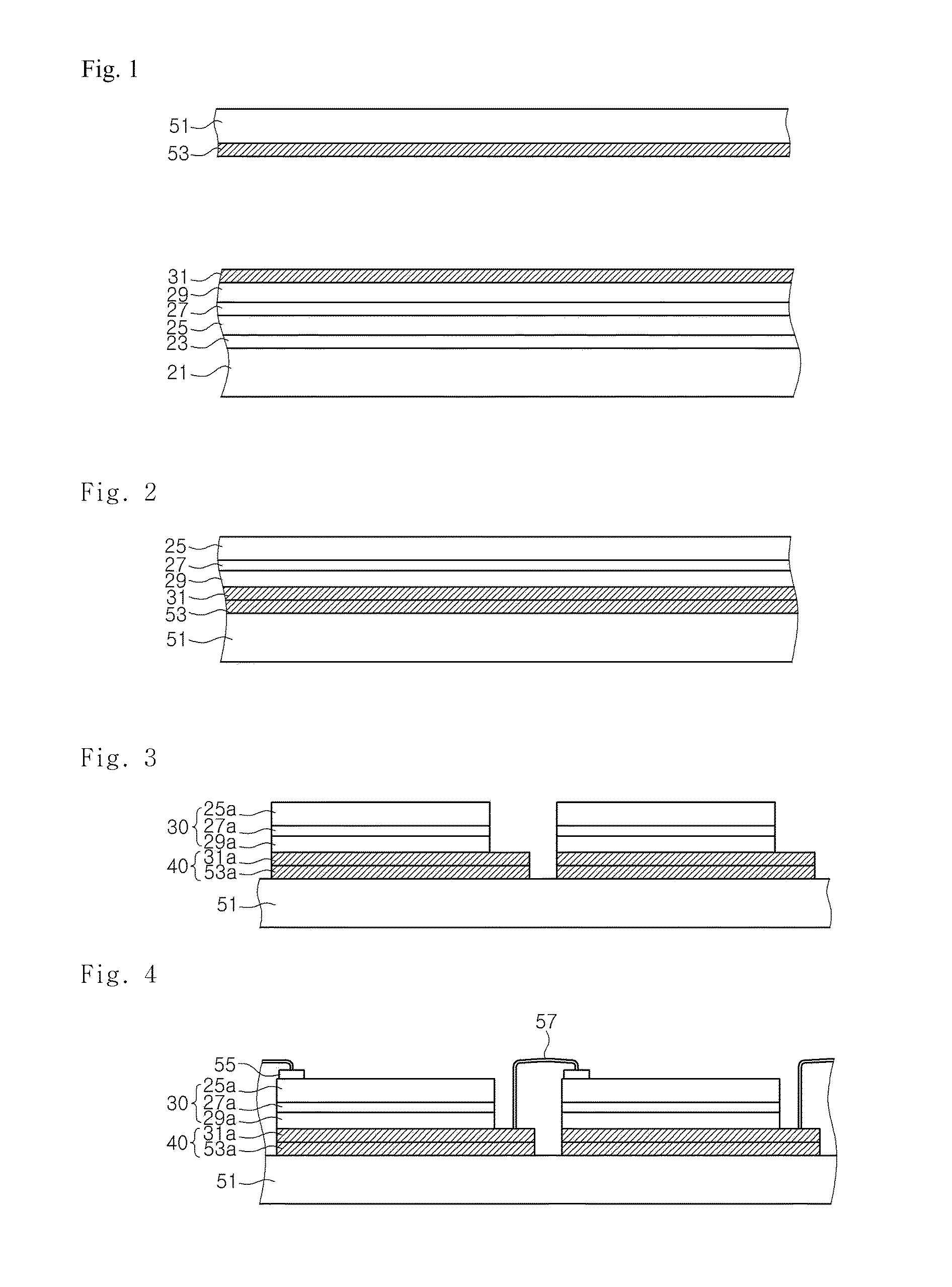
When the first metal layer 31a comprises a reflective metal layer such as Ag or Al, such etching damage may be serious.
Since the surface of the metal layer 31a is damaged by plasma, the adhesion of the wires 57 or electrode pads formed on the metal layer 31a is lowered, resulting in a device failure.
However, it is difficult to expect that light is reflected in spaces between the light emitting cells 30 due to the etching damage or oxidation of the reflective layer.

Method used


Image

  • Light emitting device and method of fabricating the same
  • Light emitting device and method of fabricating the same
  • Light emitting device and method of fabricating the same

Examples


Embodiment Construction

[0043]The invention is described more fully hereinafter with reference to the accompanying drawings, in which exemplary embodiments of the invention are shown. This invention may, however, be embodied in many different forms and should not be construed as limited to the embodiments set forth herein. Rather, these exemplary embodiments are provided so that this disclosure is thorough, and will fully convey the scope of the invention to those skilled in the art. In the drawings, the size and relative sizes of layers and regions may be exaggerated for clarity. Like reference numerals in the drawings denote like elements.

[0044]It will be understood that when an element or layer is referred to as being “on” or “connected to” another element or layer, it can be directly on or directly connected to the other element or layer, or intervening elements or layers may be present. In contrast, when an element is referred to as being “directly on” or “directly connected to” another element or lay...


PUM


Abstract

Disclosed are a light emitting device and a method of fabricating the same. The light emitting device comprises a substrate. A plurality of light emitting cells are disposed on top of the substrate to be spaced apart from one another. Each of the light emitting cells comprises a first upper semiconductor layer, an active layer, and a second lower semiconductor layer. Reflective metal layers are positioned between the substrate and the light emitting cells. The reflective metal layers are prevented from being exposed to the outside.

Description

CROSS-REFERENCE TO RELATED APPLICATIONS[0001]This application claims priority from and the benefit of Korean Patent Application No. 10-2008-0095926, filed on Sep. 30, 2008, and Korean Patent Application No. 10-2008-0095927, filed on Sep. 30, 2008, which are hereby incorporated by reference for all purposes as if fully set forth herein.BACKGROUND OF THE INVENTION[0002]1. Field of the Invention[0003]Exemplary embodiments of the present invention relate to a light emitting device and a method of fabricating the same, and more particularly, to a light emitting device having a reflective metal layer and a method of fabricating the same.[0004]2. Discussion of the Background[0005]In general, since Group-III-element nitride semiconductors, such as GaN and AlGaN, have excellent thermal stability and a direct-transition-type energy band structure, they have recently come into the spotlight as materials for light emitting devices in blue and ultraviolet regions. Particularly, blue and green li...

Claims


Application Information

Patent Timeline
IPC IPC(8): H01L33/00
CPCH01L27/156H01L33/0079H01L33/46H01L33/62H01L2924/0002H01L25/0753H01L2924/00H01L33/0093H01L33/007H01L33/06H01L33/22H01L33/32H01L33/60H01L2933/0058H01L2933/0066
Inventor SEO, WON CHEOLLEE, JOON HEEYOU, JONG KYUNKIM, CHANG YOUNSHIN, JIN CHEULKIM, HWA MOKLEE, JANG WOOYOON, YEO JINKIM, JONG KYU
Owner SEOUL VIOSYS CO LTD
Learn More