Image processing method, image processing apparatus, image pickup apparatus, and storage medium

a technology of image processing and image pickup, applied in the field of image processing technology, can solve the problems of image restoration filter which is not optimized for the out-of-focus part, the noise component is amplified along with the deteriorated image, and the image cannot be improved. , to achieve the effect of suppressing the generation of false colors

Active Publication Date: 2010-04-01
CANON KK
View PDF10 Cites 40 Cited by
  • Summary
  • Abstract
  • Description
  • Claims
  • Application Information

AI Technical Summary

Benefits of technology

[0024]The present invention provides an image processing method, an image processing apparatus, and an image pickup

Problems solved by technology

Therefore, when the image restoration filter made by using a complete inverse of the optical transfer function (OTF) as described above is used, the noise component is amplified along with the deteriorated image and generally a good image can not be obtained.
However, in taking an actual image, there may be a possibility that a state of the optical system in obtaining an input image and a state of the optical system corresponding to the image restoration filter which is applied to the input image do not match each other.
However, an image restoration filter which is not optimized for the out-of-focus part

Method used


Image

  • Image processing method, image processing apparatus, image pickup apparatus, and storage medium
  • Image processing method, image processing apparatus, image pickup apparatus, and storage medium
  • Image processing method, image processing apparatus, image pickup apparatus, and storage medium

Examples


embodiment 1

[0043]In the present embodiment, each pixel of a color input image obtained by taking an image contains a signal value for each color component of R, G, or B. As an amount of characteristics relating to a color of a pixel, a ratio of signal values between R, G, and B (brightness ratio) is defined as a color difference. Generally, the color difference is, for example, used as a value ΔE calculated from the following definition expression in an L*a*b* color space. In the embodiment, it is defined as a ratio of mutual signal values between R, G, and B.

ΔE=[(ΔL*)2+(Δa*)2+(Δb*)2]1 / 2

[0044]The color difference in the embodiment is not limited to the ratio of the signal values described above, but a difference of mutual signal values between R, G, and B under certain conditions may also be adopted.

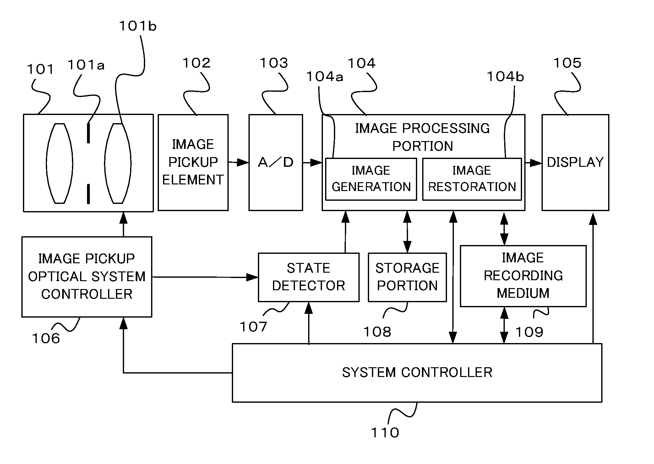
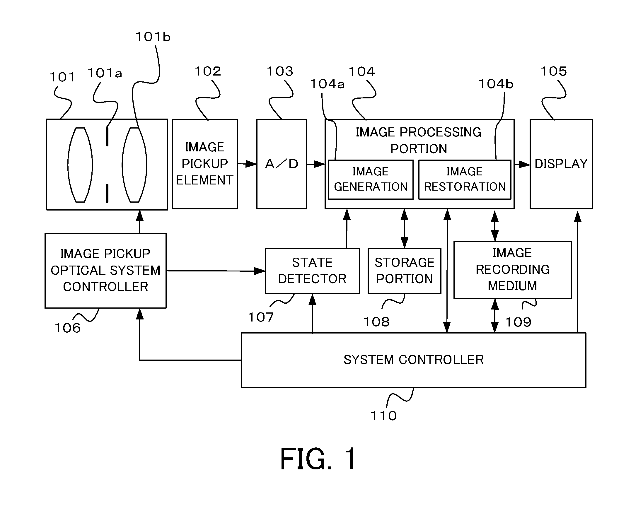
[0045]FIG. 1 shows a configuration of an image pickup apparatus such as a digital camera or a video camera which includes an image processing apparatus that is Embodiment 1 of the present inventio...

embodiment 2

[0113]Next, Embodiment 2 of the present invention will be described. An image processing method of the present embodiment is also performed by the same image pickup apparatus as that of Embodiment 1. Therefore, in the present embodiment, elements common to or having the same functions as those of Embodiment 1 are denoted by the same reference numerals as those of Embodiment 1. The process of the present embodiment may also be performed by a personal computer (image processing apparatus).

[0114]In Embodiment 1, the case where one pixel of an input image has signal values of three color components of R, G, and B has been described. On the other hand, in the present embodiment, a case where one pixel of an input image is a RAW image which has only one signal value of any one color component selected from among R, G, and B will be described. The RAW image is generated by using a pixel sensor (image pickup element) in which a color filters of R, G, and B are arrayed in a Bayer array.

[0115...


PUM


Abstract

An image processing method comprises obtaining a color input image obtained by taking an image using an optical system 101, calculating an amount of characteristics relating to a color of a pixel in the input image as a first calculating step (S4), performing an image restoration process for the input image using an image restoration filter selected or made based on aberration information of the optical system (S5), calculating an amount of characteristics relating to a color of a pixel of a restored image obtained by the image restoration process as a second calculating step (S6), and correcting a signal value of a specific pixel in the restored image in accordance with the amount of characteristics of the specific pixel in the restored image calculated by the second calculating step and the amount of characteristics of a specific pixel of the input image calculated by the first calculating step (S8).

Description

BACKGROUND OF THE INVENTION[0001]1. Field of the Invention[0002]The present invention relates to an image processing technology which reduces a blur component contained in an image by an image restoration process.[0003]2. Description of the Related Art[0004]An image obtained by imaging an object using an image pickup apparatus such as a digital camera contains a blur component as an image deteriorating component which is caused by a spherical aberration, comatic aberration, a field curvature, or astigmatism of an image pickup optical system (hereinafter, referred to simply as an “optical system”), or the like. Such a blur component is generated by forming an image with a certain spread although a light beam emitted from one point of an object is ideally focused on one point on an imaging plane again if there is no influence of diffraction without any aberrations.[0005]The blur component is optically represented by a point spread function (PSF), and is different from a blur caused by...

Claims


Application Information

Patent Timeline
IPC IPC(8): H04N9/73G06K9/00
CPCG06T2207/10024G06T2207/20056G06T5/20G06T5/003H04N9/045H04N25/611
Inventor HATAKEYAMA, KOSHI
Owner CANON KK
Why Eureka
Try Eureka