Image processing apparatus, imaging device, image processing method, and computer program product

a technology of image processing and image processing method, which is applied in the field of image processing apparatus, imaging device, image processing method, and computer program product, can solve the problems of unsuitable landweber method for noise control and ineffective use of original resolution

Inactive Publication Date: 2010-04-01
KK TOSHIBA
View PDF9 Cites 25 Cited by
  • Summary
  • Abstract
  • Description
  • Claims
  • Application Information

AI Technical Summary

Benefits of technology

[0010]According to another aspect of the present invention, an imaging device includes a lens that collects an external beam; an image sensor that accepts the the external beam via the lens and outputs image data as input image data; a blur reproducing unit that generates blur-reproduced image data by reproducing a predetermined blur of the lens, with respect to blur-corrected image data of which an initial data is the input image data; a blur correcting unit that corrects the blur-correcte

Problems solved by technology

Although the use of the Landweber method makes it possible to compensate for a reduction of a relative performance of the lens, the Landweber method is not suitable to control noise.
Consequently, the i

Method used


Image

  • Image processing apparatus, imaging device, image processing method, and computer program product
  • Image processing apparatus, imaging device, image processing method, and computer program product
  • Image processing apparatus, imaging device, image processing method, and computer program product

Examples


first embodiment

[0050]In the first embodiment, image data of which color filter arrangement is obtained from the single-pixel image sensor of the Bayer arrangement is processed. However, the embodiments of the present invention are not limited to the Bayer arrangement, and other color filter arrangements can be used.

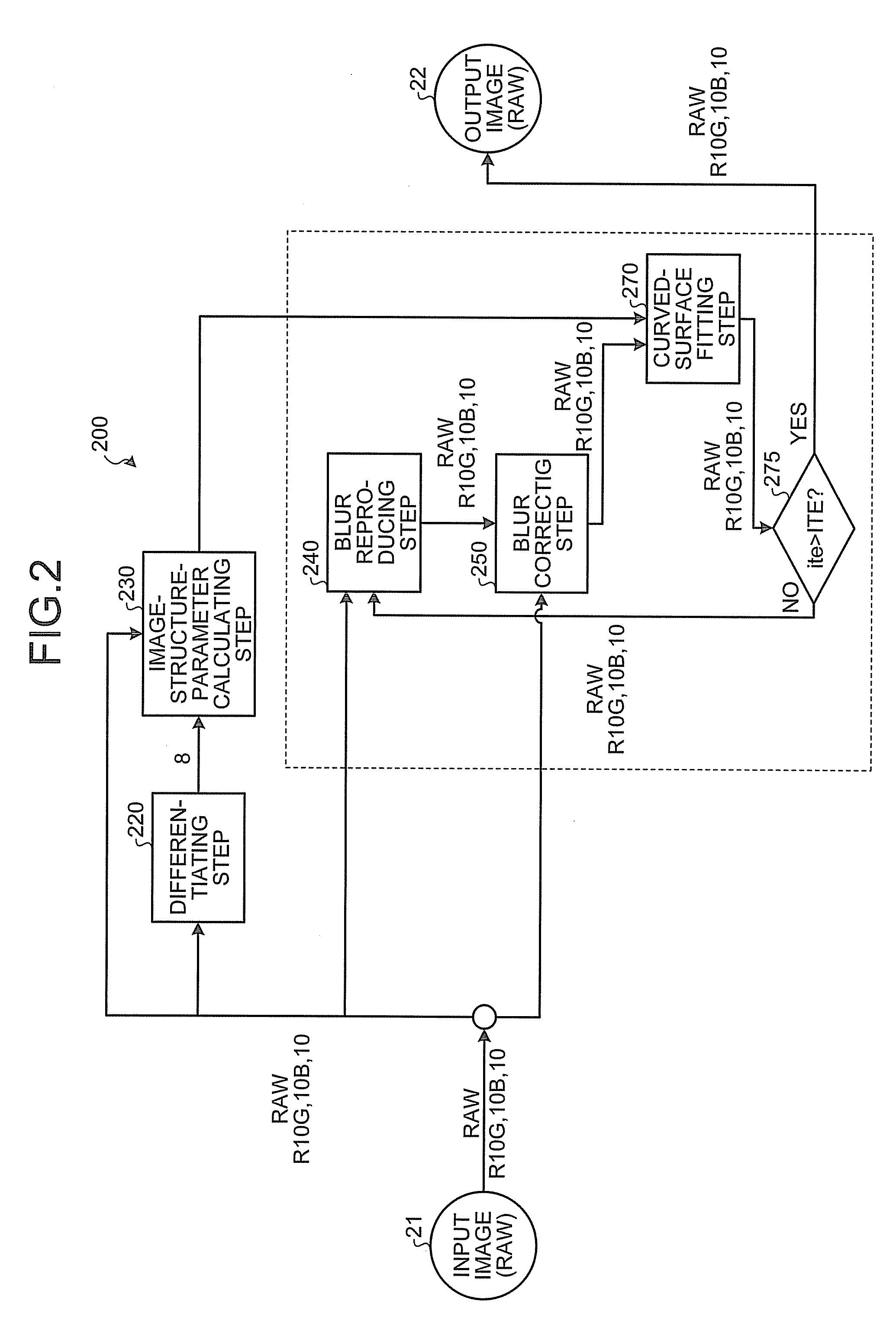
[0051]Details of the image processing method according to the first embodiment will be explained below for each step shown in FIG. 2. Image data output from the image sensor is called RAW data here. The RAW data of a pixel position i=(i, j)T is expressed as yi. A color filter arrangement is expressed as ci∈{R, G, B}. A corrected image to be obtained is expressed as xi. How an image is blurred by optical blur can be described by a point spread function (hereinafter, “PSF”). A PSF of a color ci at a local position s=(s, t)T centered around a pixel position i is expressed as h(s, i, ci). This PSF is known. The PSF can be obtained in advance by simulation or measurement based on a design va...

second embodiment

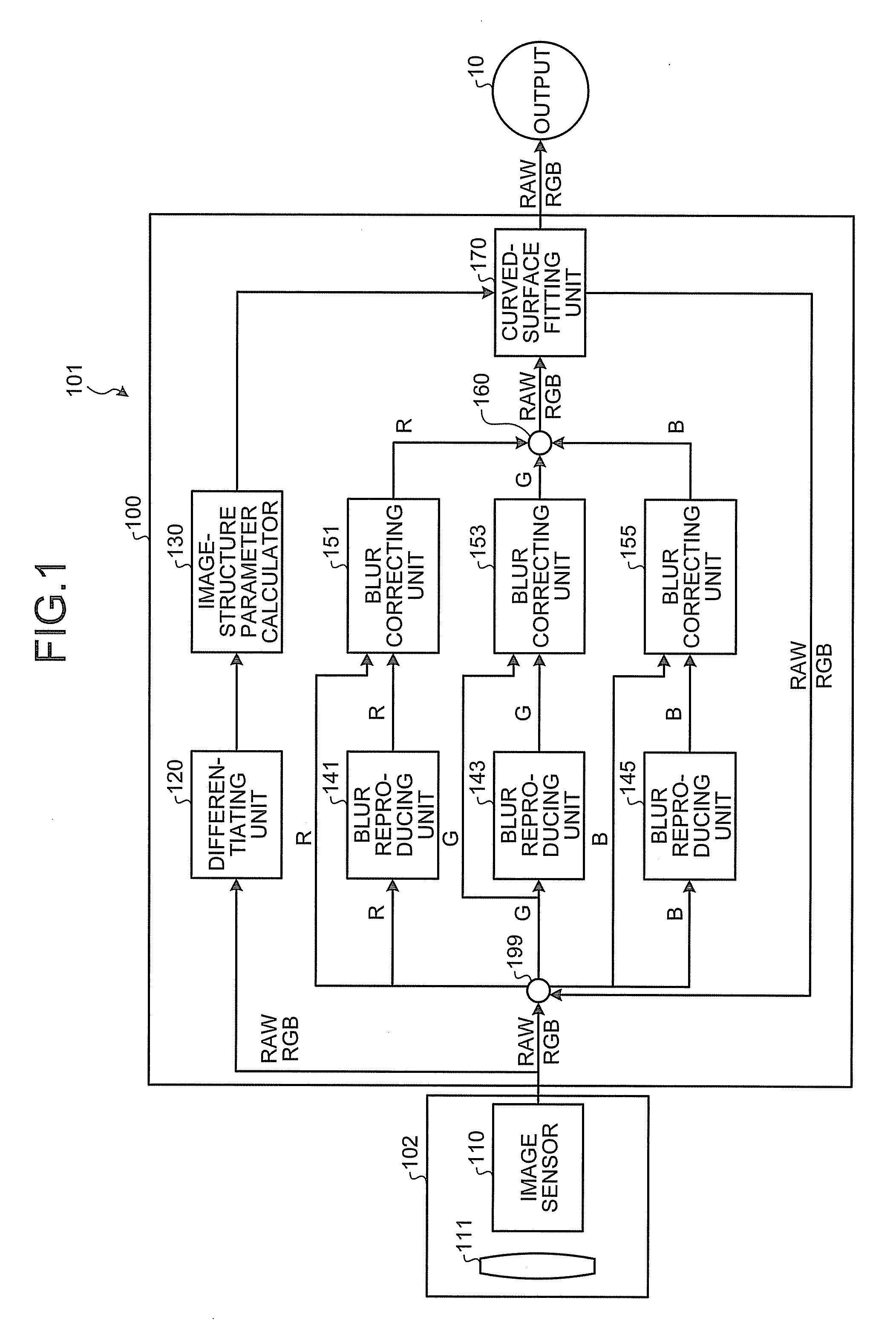
[0109]FIG. 17 is a block diagram illustrating a functional configuration of an imaging device according to the present invention. The imaging device 101a includes an imaging unit 102 and an image processing apparatus 100a in FIG. 17.

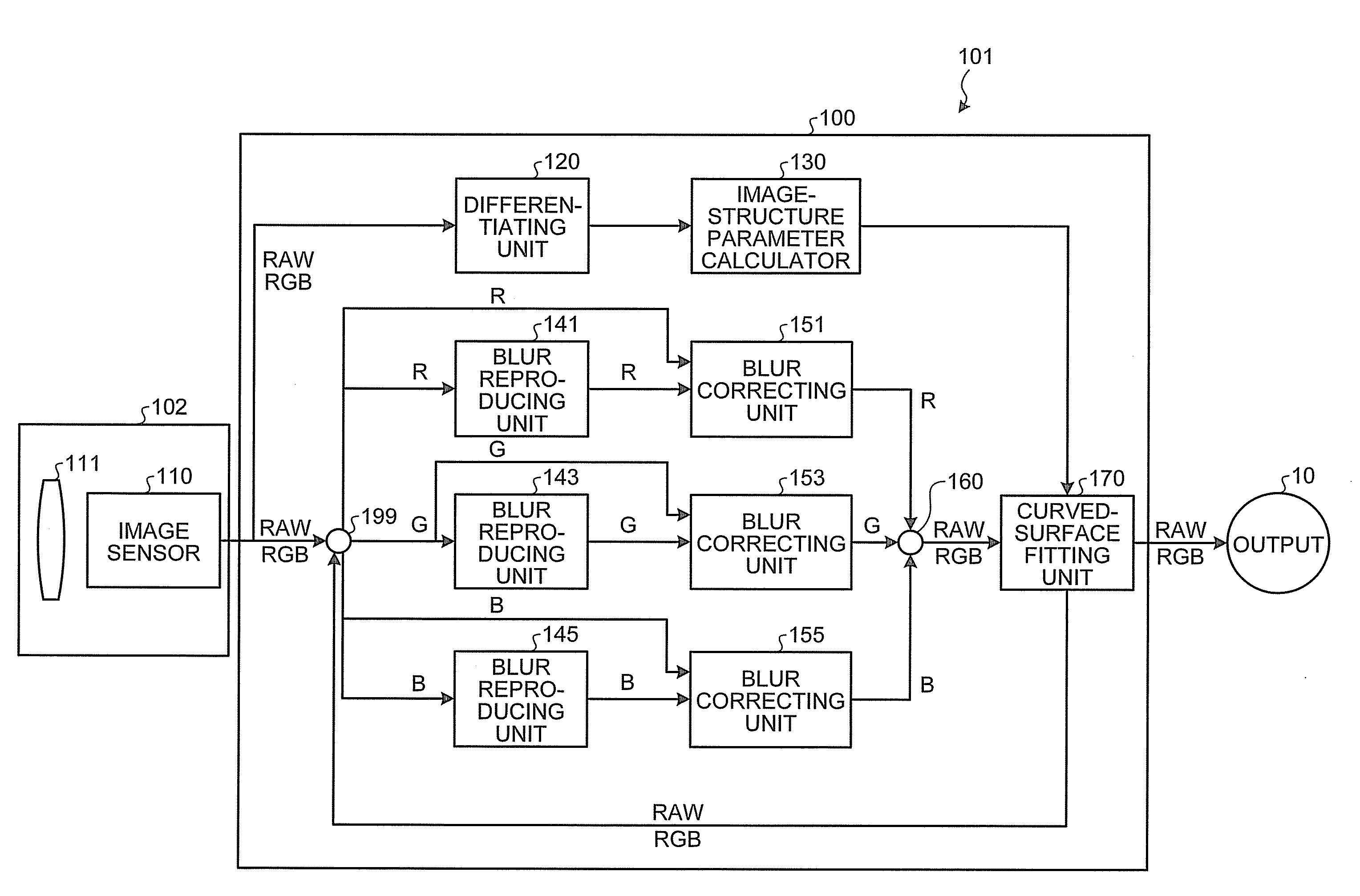
[0110]An image processing apparatus 100a in FIG. 17 includes the image sensor 110, the differentiating unit 120, the image-structure parameter calculator 130, the blur reproducing unit 141, the blur reproducing unit 143, the blur reproducing unit 145, the blur correcting unit 151, the blur correcting unit 153, the blur correcting unit 155, the multiplexer 160, a filter selecting unit 180, a filtering unit 190, and the demultiplexer 199.

[0111]In FIG. 17, blocks having the same functions and the same configurations as those of the imaging device 101 in FIG. 1 are assigned with like reference numerals, and explanations thereof will be omitted here.

[0112]The filter selecting unit 180 selects a filter from a lookup table (hereinafter, “LUT”) storing filter co...


PUM


Abstract

An image processing apparatus includes a blur reproducing unit that generates blur-reproduced image data by reproducing a predetermined blur of a lens, with respect to blur-corrected image data of which an initial data is input image data inputted from an image sensor; a blur correcting unit that corrects the blur-corrected image data so that an error between the blur-reproduced image data and the input image data becomes smaller; and a curved-surface fitting unit that obtains curve surface parameters of each functions approximating distribution of pixel values of each of color components of the blur-corrected image data so that curved-surface shapes of the functions become the same among the color components, and updates the pixel values of the blur-corrected image data by using the curve surface parameters.

Description

CROSS-REFERENCE TO RELATED APPLICATIONS[0001]This application is based upon and claims the benefit of priority from the prior Japanese Patent Application No. 2008-251658, filed on Sep. 29, 2008; the entire contents of which are incorporated herein by reference.BACKGROUND OF THE INVENTION[0002]1. Field of the Invention[0003]The present invention relates to an image processing apparatus, an imaging device, an image processing method, and a computer program product.[0004]2. Description of the Related Art[0005]Conventionally, there are techniques of correcting various aberrations included in an image output from an image sensor. When an external light beam is collected on an image sensor by a lens, the image sensor photoelectrically converts the light beam into a charge and accumulates charges. Even when the image sensor corresponds to higher resolution, an image blur occurs when condensation of the lens does not correspond to the resolution.[0006]For example, “Iterative methods for ima...

Claims


Application Information

Patent Timeline
IPC IPC(8): G06K9/40H04N9/64
CPCG06T7/0085G06T2207/10024G06T5/003G06T5/002H04N9/045G06T7/13
Inventor MISHIMA, NAOISOGAWA, KENZOBABA, MASAHIRO
Owner KK TOSHIBA
Why Eureka
Try Eureka