
Two frequency resonantly excited MEMS mirror for diode-laser marker

a diode-laser marker and mems mirror technology, applied in the field of mems mirrors, can solve the problems of putting such a system beyond the means of the majority of smaller industrial or commercial users, and cost about two orders of magnitude greater

Inactive Publication Date: 2010-04-01
COHERENT INC
View PDF10 Cites 20 Cited by
  • Summary
  • Abstract
  • Description
  • Claims
  • Application Information

AI Technical Summary

Benefits of technology

The present invention is about a micro-electro-mechanical system (MEMS) that includes a support-frame with a torsion-beam connected to it. A mirror and a counter-mass are separately connected to the torsion-beam. Actuators are connected to the torsion-beam for exciting the mirror and counter-mass to torsional resonance. The torsion-beam, the frame, and the counter-mass are configured such that the mirror and counter-mass have first and second torsional-resonance modes at respectively first and second frequencies, with the second frequency being about an integer multiple of the first frequency. The oscillating mirror is useful as a scanning mirror for a laser beam. The actuators are driven by piezoelectric elements by an AC voltage applied thereto. The technical effect of this invention is to provide a MEMS that can efficiently and accurately scan a laser beam in a compact design.

Problems solved by technology

Even the least expensive laser marking system designed for these label materials has a cost about two orders of magnitude greater than a computer peripheral paper-label printer such as an inkjet printer, which puts such a system beyond the means of the majority of smaller industrial or commercial users.
This is somewhat unfortunate as such a system does not require periodic replacement of inkjet or toner cartridges and will function until the laser eventually fails which may only be after tens of thousands of hours of actual use.

Method used


Image

  • Two frequency resonantly excited MEMS mirror for diode-laser marker
  • Two frequency resonantly excited MEMS mirror for diode-laser marker
  • Two frequency resonantly excited MEMS mirror for diode-laser marker

Examples


Embodiment Construction

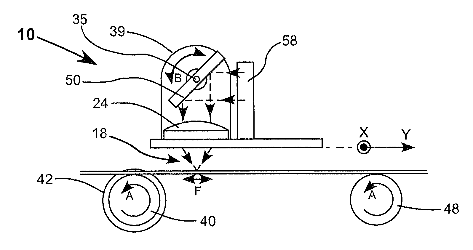
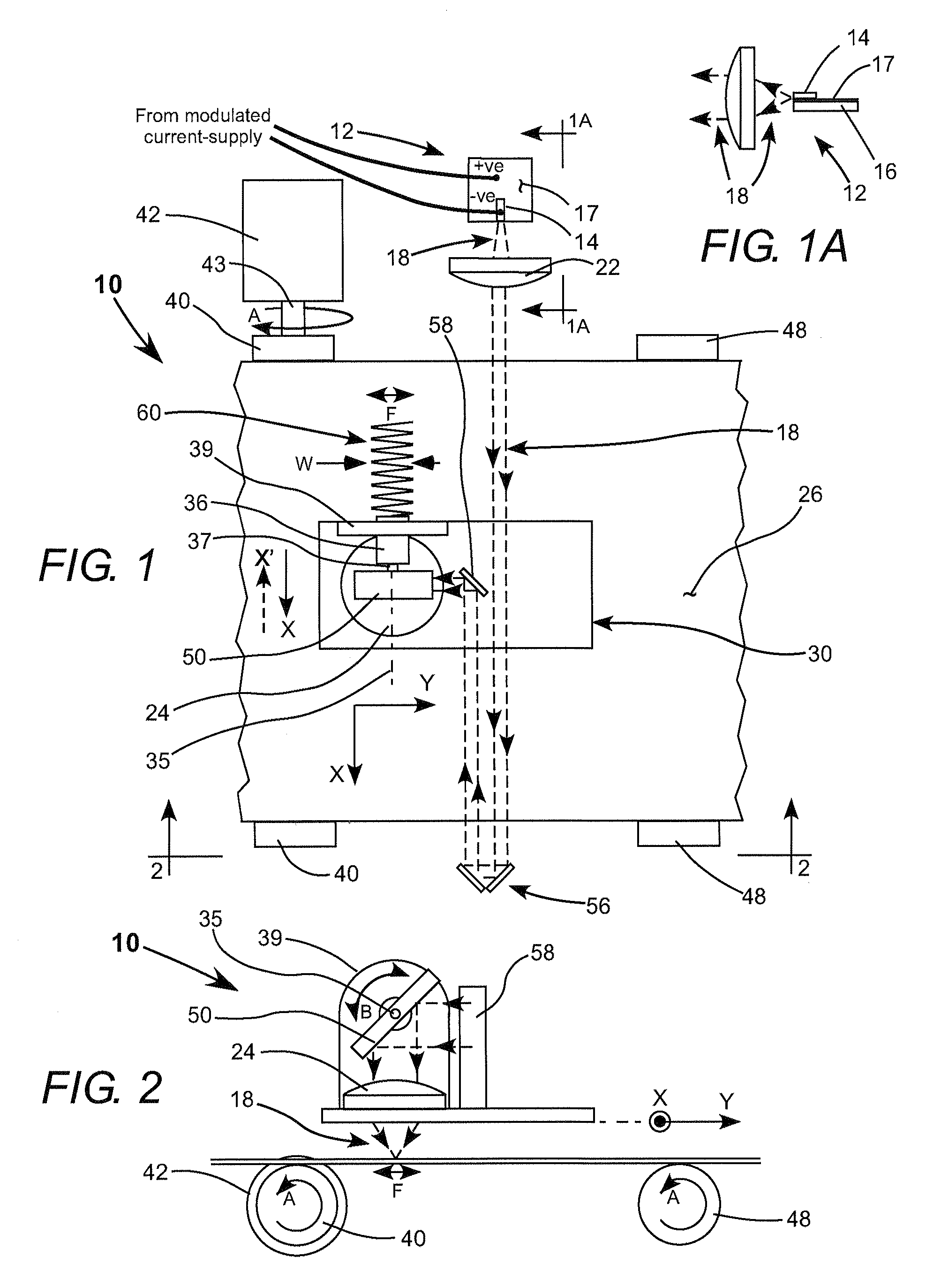
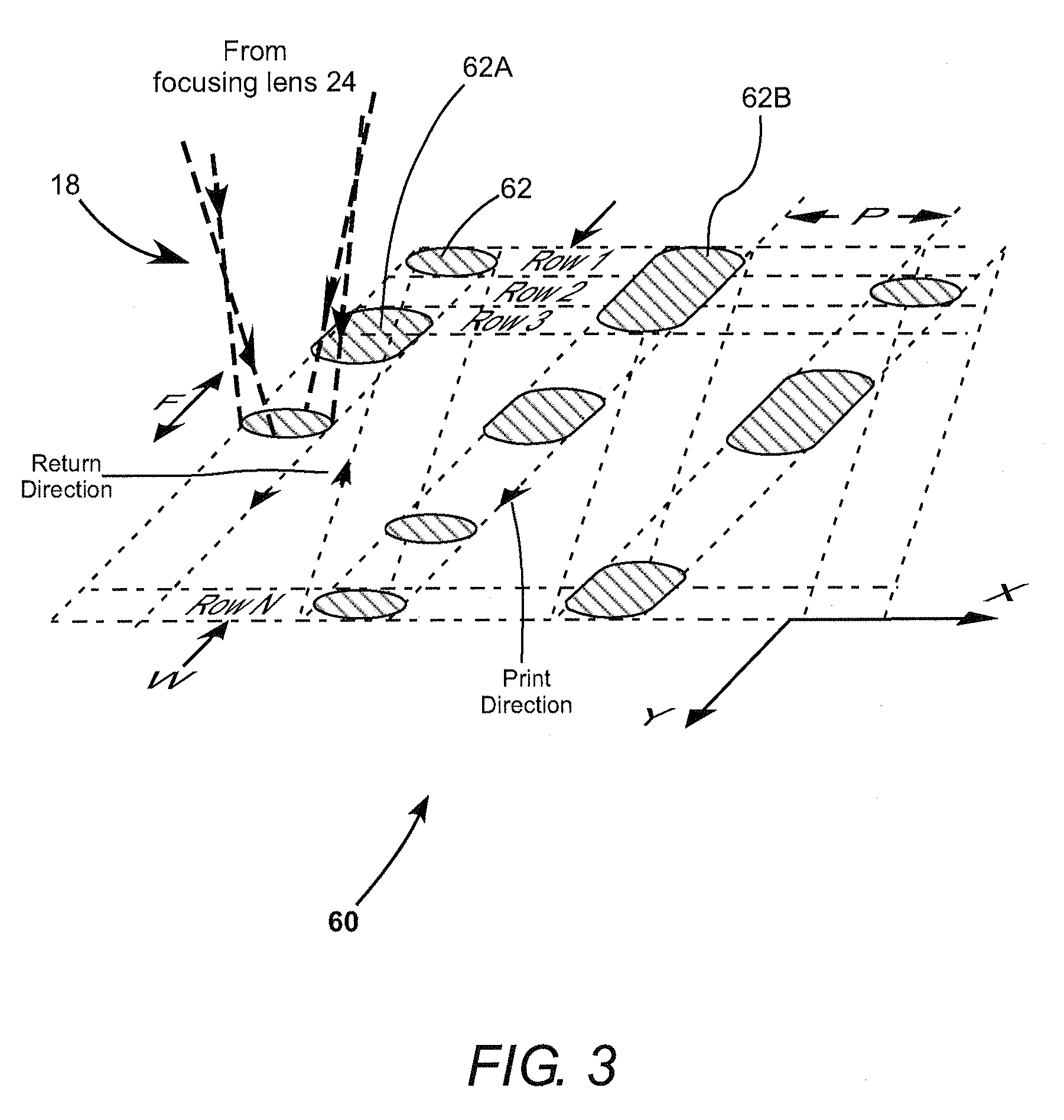
[0022]Referring now to the drawings, wherein like components are designated by like reference numerals, FIG. 1, FIG. 1A and FIG. 2 schematically illustrates one preferred embodiment 10 of laser marking apparatus in accordance with the present invention. Apparatus 10 includes a diode-laser 12 including an edge-emitting semiconductor heterostructure (emitter) 14 on an insulating sub-mount 16. The sub-mount has a metallization layer 17 thereon to which the emitter is soldered. A heat-sink for cooling the sub-mount is preferably provided but is not shown in the drawings for simplicity of illustration.

[0023]Emitter 14 emits a beam 18 diverging in the fast axis of the emitter at an angle of about 30° measured across the FWHM intensity points of the beam(see FIG. 1A). Divergence in the slow-axis (perpendicular to the fast axis) is about 10° (see FIG. 1). These divergences should not be construed as limiting the present invention. Beam 18 from diode-laser 14 is intercepted by a lens 22, whi...


PUM


Abstract

Apparatus for marking a bitmap image on tape includes a scanning mirror which is incorporated in a micro-electro-mechanical system (MEMS). The MEMS is torsionally resonant at two frequencies one being about three time the other. The MEMS is excited to resonance by applying an AC signal to the actuators, causing the mirror to oscillate. The AC signal has components at the two frequencies. The magnitude and phase-relationship of the components can be selected such that the mirror oscillates in an approximation of a triangle-wave.

Description

TECHNICAL FIELD OF THE INVENTION[0001]The present invention relates in general MEMS mirrors useful in laser marking systems.DISCUSSION OF BACKGROUND ART[0002]Laser marking systems are now in common use for marking materials such as metals, glass, wood, and plastic. Lasers used in such marking systems include diode-pumped solid-state lasers, fiber-lasers, and carbon dioxide (CO2) lasers. Typically a beam from whatever laser is used in the system is steered by a two-axis galvanometer and focused by f-theta optics onto a surface of an object being marked.[0003]Special materials have been developed, and are commercially available, for accepting laser radiation to allow high-speed, high-volume, writing of labels with a laser marking system. One such material is “Laser Markable Label Material 7847” available from 3M Corporation of Minneapolis, Minn. This material is a three-layer polymer material having a white base film with a black surface coating to facilitate absorption of laser radia...

Claims


Application Information

Patent Timeline
Patent Type & Authority Applications(United States)
IPC IPC(8): G02B26/08
CPCB41C1/05G02B26/105B41M5/26B41M5/24G02B26/08
Inventor JERMAN, JOHN H.
Owner COHERENT INC
Learn More