Spin-torque oscillator, a magnetic sensor and a magnetic recording system

Active Publication Date: 2010-04-01
KK TOSHIBA
View PDF17 Cites 13 Cited by
  • Summary
  • Abstract
  • Description
  • Claims
  • Application Information

AI Technical Summary

Benefits of technology

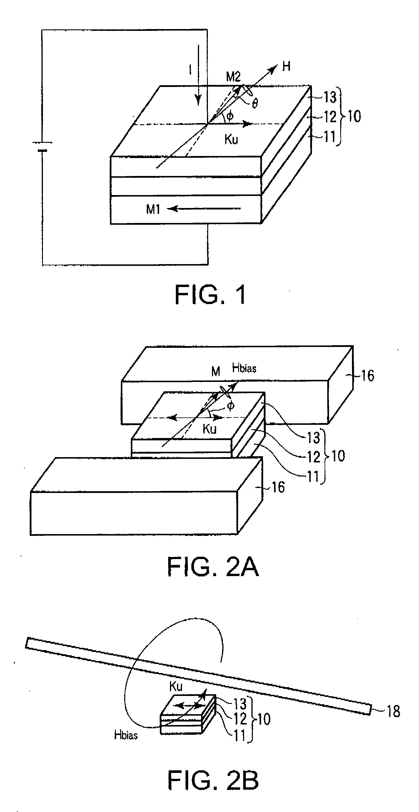
[0013]According to an aspect of the present invention, there is provided a spin-torque oscillator comprising: a first ferromagnetic layer; a non-magnetic layer stacked on the first ferromagnetic layer; a second ferromagnetic layer stacked on the non-magnetic layer; a pair of electrodes configured to perpendicularly apply a current onto each plane of the first ferromagnetic layer, the non-magnetic layer and the second ferromagnetic layer, the current inducing a precession of a magnetization of at leas

Problems solved by technology

However, in the TMR element, not only a pure signal component but also a noise component by a shot noise becomes also larger.
As a result, S/N ratio (signal to noise ratio) does not improve.
As a result, manufacture of this element is extremely difficult.
Recently, a magnetic white noise becomes a problem c

Method used


Image

  • Spin-torque oscillator, a magnetic sensor and a magnetic recording system
  • Spin-torque oscillator, a magnetic sensor and a magnetic recording system
  • Spin-torque oscillator, a magnetic sensor and a magnetic recording system

Examples


example 1

[0062]In the example 1, a method for manufacturing the spin-torque oscillator 10 and a measurement result of the oscillation characteristic are explained. FIG. 7 shows a sectional plan of the spin-torque oscillator 10 manufactured. In FIG. 7, a film is coated on a glass substrate 31 by a sputtering apparatus. An upper part electrode 33 and a lower part electrode 32 are formed by photo-lithography and ion-milling. A spin-torque oscillator 10 is processed by an electron beam-lithography and the ion-milling.

[0063]The first ferromagnetic layer 11 comprises an exchange bias film which an artificial ferrimagnetic film (an intermediate layer 23 is put into two ferromagnetic layers 22 and 24) and an antiferromagnetic layer are stacked, in which the magnetization is fixed. The intermediate layer 23 is composed by Ru, the ferromagnetic layer 22 is composed by CoFe, the ferromagnetic layer 24 is composed by CoFeB, and the antiferromagnetic layer 21 is composed by IrMn. The non-magnetic layer 1...


PUM


Abstract

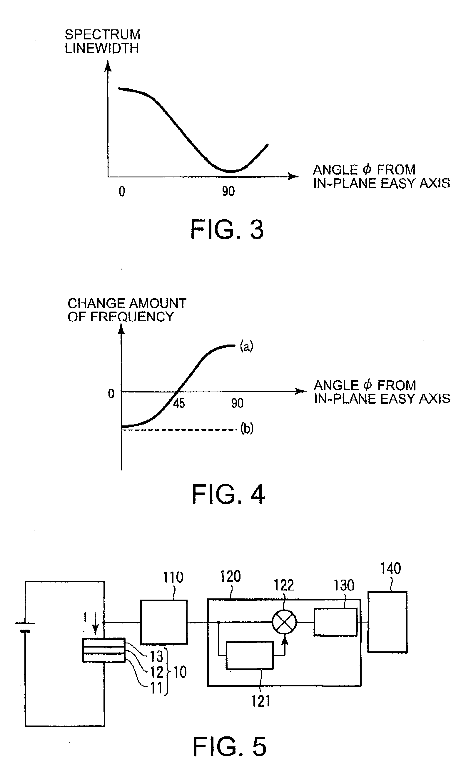
In a spin-torque oscillator, a first ferromagnetic layer, a non-magnetic layer and a second ferromagnetic layer are stacked. A pair of electrodes perpendicularly applies a current onto each plane of the first ferromagnetic layer, the non-magnetic layer and the second ferromagnetic layer. The current induces a precession of a magnetization of at least one of the first ferromagnetic layer and the second ferromagnetic layer. The at least one is formed by an in-plane magnetization film having a uniaxial magnetic anisotropy. A magnetic field generator generates a magnetic field to control a direction of the magnetization so that a non-linearity frequency shift of the precession by the uniaxial magnetic anisotropy cancels a non-linearity frequency shift of the precession by a demagnetizing field on the in-plane magnetization film.

Description

CROSS-REFERENCE TO RELATED APPLICATIONS[0001]This application is based upon and claims the benefit of priority from Japanese Patent Application No. 2008-254351, filed on Sep. 30, 2008; the entire contents of which are incorporated herein by reference.FIELD OF THE INVENTION[0002]The present invention relates to a spin-torque oscillator, a magnetic sensor having the spin-torque oscillator, and a magnetic recording system having the magnetic sensor.BACKGROUND OF THE INVENTION[0003]Since a GMR head utilizing a giant magnetoresistive effect (GMR effect) is widely spread, a recording density of a magnetic recording becomes remarkably high. A GMR element includes a multilayer (spin bulb film), i.e., a ferromagnetic layer / a non-magnetic layer / a ferromagnetic layer. In the GMR element, an exchange bias is subjected to one ferromagnetic layer to fix a magnetization, a magnetization of another ferromagnetic layer is changed by an external magnetic field, and a change of relative angle between ...

Claims


Application Information

Patent Timeline
IPC IPC(8): G11B5/127
CPCB82Y25/00G01R33/093G01R33/098G01R33/1284H01F10/329G11B2005/0002H01F10/3254H01F10/3277H01L43/08G11B5/3903H10N50/10
Inventor NAGASAWA, TAZUMIKUDO, KIWAMUMIZUSHIMA, KOICHISATO, RIE
Owner KK TOSHIBA
Why Eureka
Try Eureka