Epoxy prepolymer, and epoxy resin composition, cured material, semi-cured material, prepreg and composite substrate using the epoxy prepolymer

Inactive Publication Date: 2010-04-01
TDK CORPARATION
View PDF6 Cites 13 Cited by
  • Summary
  • Abstract
  • Description
  • Claims
  • Application Information

AI Technical Summary

Benefits of technology

[0029]When measuring the properties of the epoxy resin composition containing the above epoxy prepolymer, and the cured material thereof, the present inventors found that their thermal conductivities were considerably enhanced compared to conventional products. Although the specific mechanism that brings about the above effect is still yet to be understood, a possible mechanism is as follows:
[0030]It is believed that since the above epoxy prepolymer has, in the molecule thereof, a trinuclear skeleton (triphenyl skeleton) introduced therein, the density

Problems solved by technology

However, the thermal conductivity of the epoxy resin composition disclosed in Japa

Method used


Image

  • Epoxy prepolymer, and epoxy resin composition, cured material, semi-cured material, prepreg and composite substrate using the epoxy prepolymer
  • Epoxy prepolymer, and epoxy resin composition, cured material, semi-cured material, prepreg and composite substrate using the epoxy prepolymer
  • Epoxy prepolymer, and epoxy resin composition, cured material, semi-cured material, prepreg and composite substrate using the epoxy prepolymer

Examples


example 1

[0064]50 parts by mass of a difunctional crystalline epoxy compound represented by the formula shown below (trade name: YL6121H, product of Japan Epoxy Resins Co., Ltd., epoxy equivalent: 175) and 21.17 parts by mass of a trinuclear bisphenol (4,4″-dihydroxy-3-methyl-p-triphenyl, abbreviated as DHTP-M, equivalent: 138) were placed in a three-mouth flask (equivalent ratio: 0.5), and 166 parts by mass of methyl ethyl ketone were further added so that the solid content in the resulting mixture was 30% by mass. The resulting mixture was stirred after setting the temperature so as to bring the mixture under reflux. Upon observing the flask having reflux inside, the stirring reaction was carried out for twelve hours. After that, the mixture was cooled to room temperature, and as a result, an epoxy prepolymer of Example 1 was synthesized. In this epoxy prepolymer solution, 14.07 parts by mass (equivalent ratio: 0.5) of a biphenylaralkyl curing agent represented by the formula shown below (...

example 2

[0065]In the same manner as Example 1 other than replacing the curing agent with a biphenylaralkyl curing agent represented by the formula shown below (trade name: MEH7851, product of Meiwa Plastic Industries, Ltd., equivalent: 212, average n=10, softening point=73° C.), an epoxy resin composition of Example 2 was prepared.


PUM

PropertyMeasurementUnit
Percent by massaaaaaaaaaa
Thermal conductivityaaaaaaaaaa

Abstract

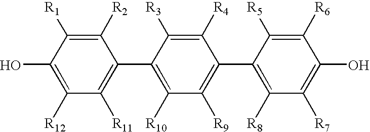
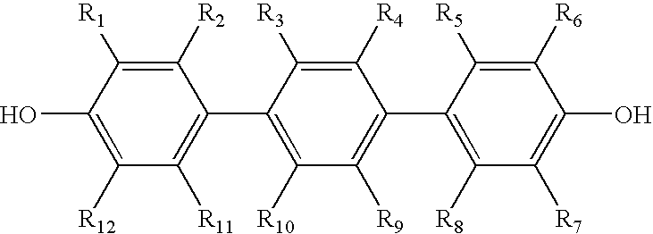
An epoxy prepolymer having excellent thermal conductivity is obtained by reacting an epoxy compound having a mesogenic skeleton and a trinuclear bisphenol represented by the following formula:
(wherein each of R1, R2, R3, R4, R5, R6, R7, R8, R9, R10, R11 and R12 represents a hydrogen atom or an alkyl group and each may be the same or different while at least one represents an alkyl group).

Description


Claims


Application Information

Patent Timeline
Owner TDK CORPARATION
Why Eureka
Try Eureka