Dressing method, method of determining dressing conditions, program for determining dressing conditions, and polishing apparatus

a dressing method and dressing technology, applied in the direction of grinding drives, grinding drives, manufacturing tools, etc., can solve the problems of lowering the polishing rate, polishing failure, and variation (or disorder) in the polishing rate of the polished surface of the workpi

Active Publication Date: 2010-04-01
EBARA CORP
View PDF16 Cites 39 Cited by
  • Summary
  • Abstract
  • Description
  • Claims
  • Application Information

AI Technical Summary

Benefits of technology

[0044]According to the present invention, in dressing of the polishing member with the diamond dresser, the dressing conditions can be determined using the more accurate simulation than a conventional si

Problems solved by technology

However, continuous polishing operations for the workpieces with use of the polishing member can crush the fine irregularities on the surface of the polishing member, thus causing a lowered polishing rate.
Therefore, if dressing is not performed appropriately, unwanted undulation is formed on the surface of the polishing member, causing variation (or disorder) in a polishing rate within the polished surface of the workpiece when polishing.
Such variation in the polishing rate can be a possible cause of polishing failure.
While the rotational speed of the polishing member, the rotational speed of the dresser, the dressing load, and the moving speed of the dresser can be controlled independently, these elements affect an amount of the polishing member to be scraped off in a complicated manner.
In particular, in the dressing operation with use of the small-diameter dresser, determination of the dressing conditions from experiments requires a lot of time and labors.
However, in the known method, the simulation result of the s

Method used


Image

  • Dressing method, method of determining dressing conditions, program for determining dressing conditions, and polishing apparatus
  • Dressing method, method of determining dressing conditions, program for determining dressing conditions, and polishing apparatus
  • Dressing method, method of determining dressing conditions, program for determining dressing conditions, and polishing apparatus

Examples


Embodiment Construction

[0066]A dressing method using a small-diameter dresser according to an embodiment of the present invention will be described with reference to the drawings. This dressing method is suitable for dressing a polishing pad (polishing member) used in a polishing apparatus for polishing a workpiece, such as a semiconductor wafer.

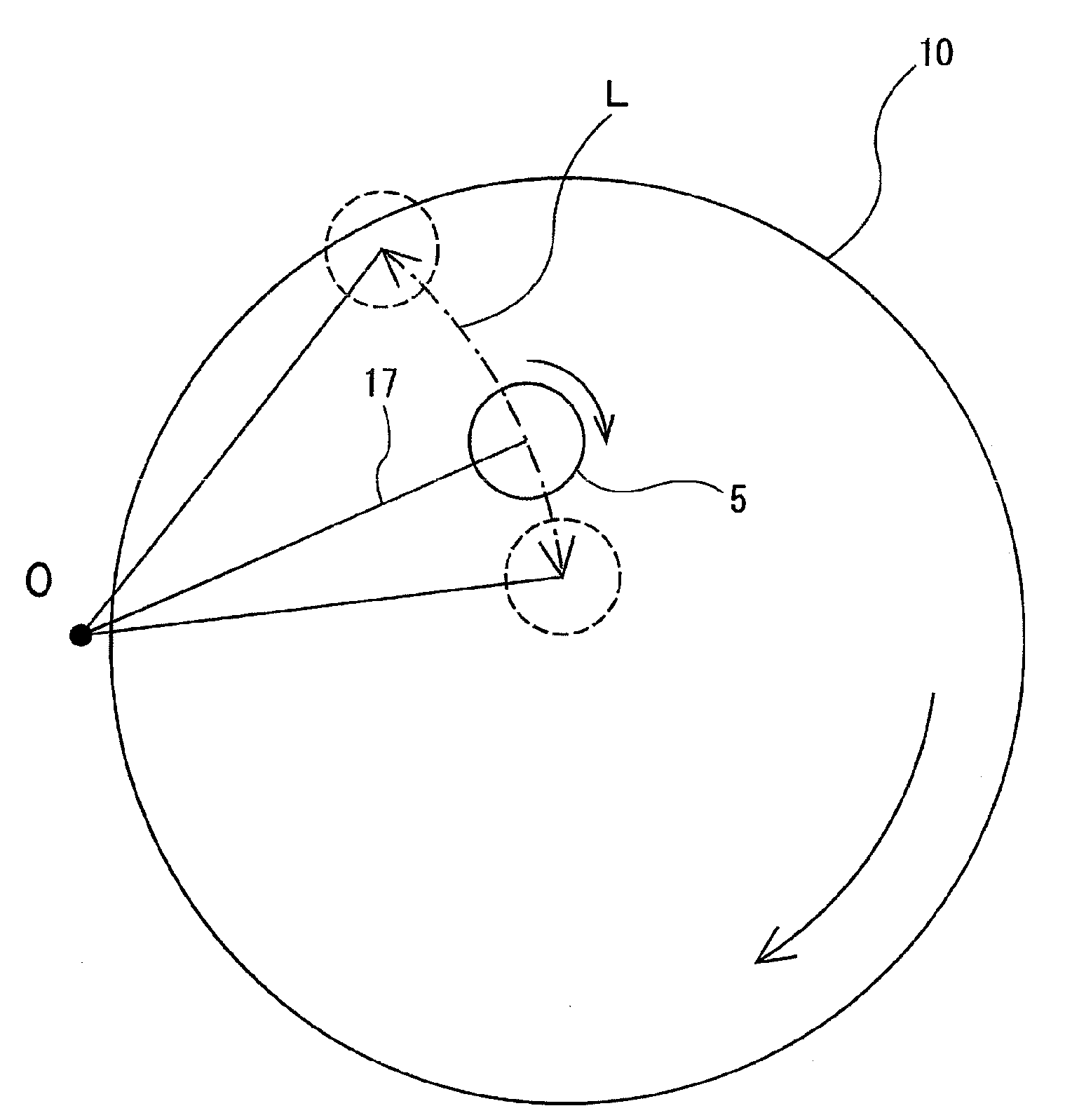
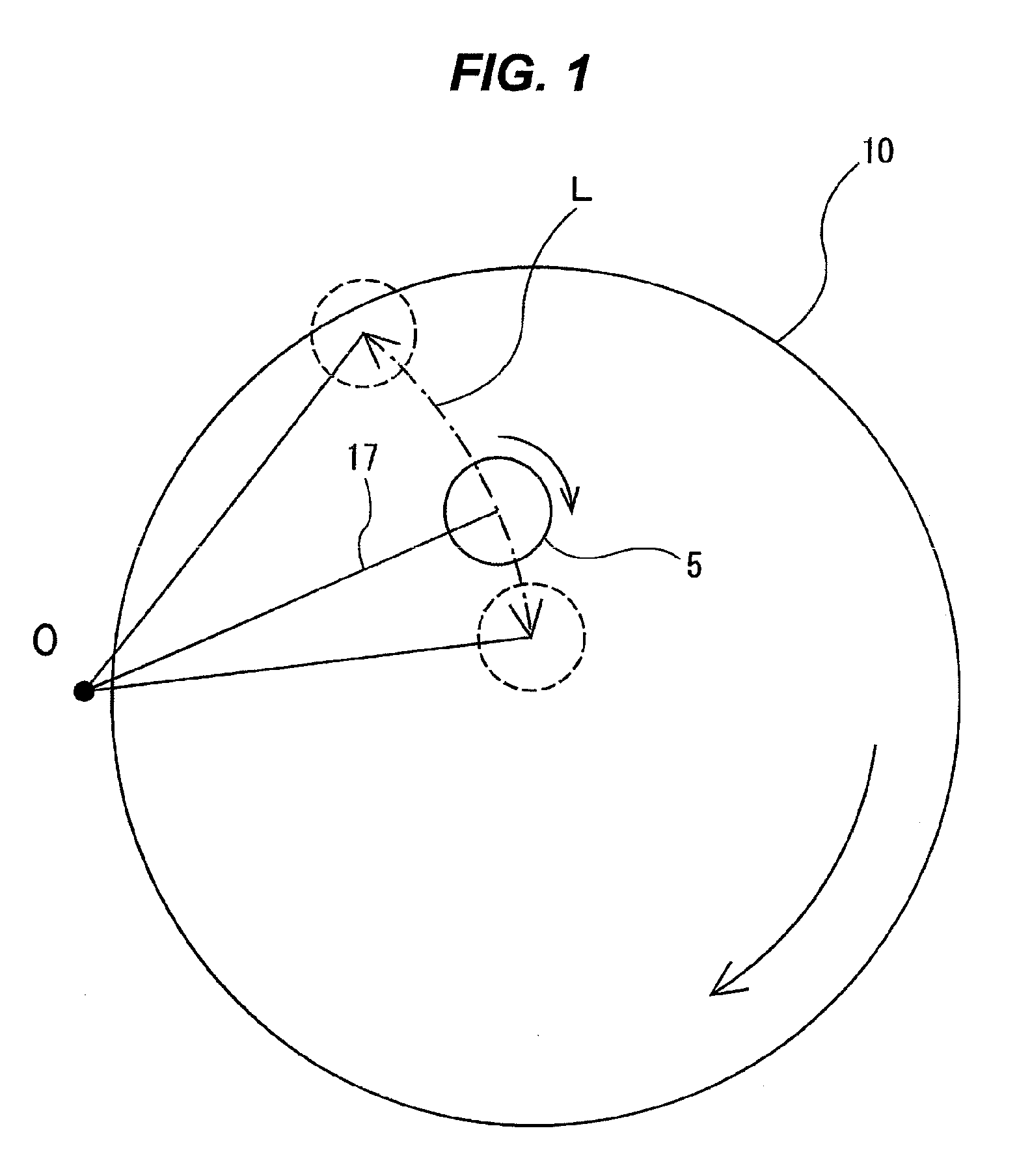
[0067]FIG. 3 is a schematic view showing a diamond dresser 5 when dressing a polishing pad 10 as viewed from a lateral direction. As shown in FIG. 3, the diamond dresser 5 is coupled to a dresser rotational shaft 16 via a universal joint 15. The dresser rotational shaft 16 is coupled to a non-illustrated rotating device. The dresser rotational shaft 16 is rotatably supported by a dresser arm 17, and the dresser 5 is swung by the dresser arm 17 as shown in FIG. 1 while contacting the polishing pad 10. The universal joint 15 is configured to transmit rotation of the dresser rotational shaft 16 to the dresser 5 while allowing tilting motion of the dresser 5. The dres...


PUM

PropertyMeasurementUnit
Depthaaaaaaaaaa
Distanceaaaaaaaaaa
Sliding frictionaaaaaaaaaa

Abstract

A method of dressing a polishing member with a diamond dresser having diamond particles arranged on a surface thereof is provided. The method includes determining dressing conditions by performing a simulation of a distribution of a sliding distance of the diamond dresser on a surface of the polishing member, and dressing the polishing member with the diamond dresser under the dressing conditions determined. The simulation includes calculation of the sliding distance corrected in accordance with a depth of the diamond particles thrusting into the polishing member.

Description

BACKGROUND OF THE INVENTION[0001]1. Field of the Invention[0002]The present invention relates to a method of dressing a polishing member, which is used in a polishing apparatus for polishing a workpiece (e.g., an optical parts, a mechanical parts, ceramics, and metal), by a diamond dresser and also relates to a method of determining dressing conditions, a program for determining dressing conditions, and a polishing apparatus. More particularly, the present invention relates to a dressing method, a method of determining dressing conditions, and a program for determining dressing conditions suitable for a polishing pad of a polishing apparatus that polishes a workpiece, such as a semiconductor wafer, to provide a planarized surface, and also relates to such a polishing apparatus.[0003]2. Description of the Related Art[0004]As a more highly integrated structure of a semiconductor device has recently been developed, interconnects of a circuit become finer and dimensions of the integrate...

Claims


Application Information

Patent Timeline
IPC IPC(8): B24B53/02B24B1/00B24B53/12B24B53/00B24B53/017H01L21/304
CPCB24B53/017
Inventor FUKUDA, AKIRAMOCHIZUKI, YOSHIHIROWADA, YUTAKASHIOKAWA, YOICHIHIYAMA, HIROKUNI
Owner EBARA CORP
Why Eureka
Try Eureka