Ship Rudder Control (Autopilot) with a CAN Bus

a can bus and rudder technology, applied in the direction of steering components, floating buildings, transmission, etc., can solve the problems of single component failure, large overhead in information transmission, and the inability to use two data buses simultaneously, so as to avoid contradictory information from being transmitted

Active Publication Date: 2010-04-01
RAYTHEON ANSCHIITZ GMBH
View PDF4 Cites 11 Cited by
  • Summary
  • Abstract
  • Description
  • Claims
  • Application Information

AI Technical Summary

Benefits of technology

[0010]By simply comparing the address signals, a component can now take the decision of which of the two buses is to be used. For example, that component with the lowest address (e.g. the lowest bit value) can be selected as a monitoring component. In this way the

Problems solved by technology

When using electronic components with a CAN bus, as is customary in automotive engineering, there is the problem that outages of single components are often due to poor functional capability of a bus interface or the cabling or the plug connection of the electronic component to the bus.
The bus can further be damaged in its property as d

Method used


Image

  • Ship Rudder Control (Autopilot) with a CAN Bus
  • Ship Rudder Control (Autopilot) with a CAN Bus
  • Ship Rudder Control (Autopilot) with a CAN Bus

Examples


Embodiment Construction

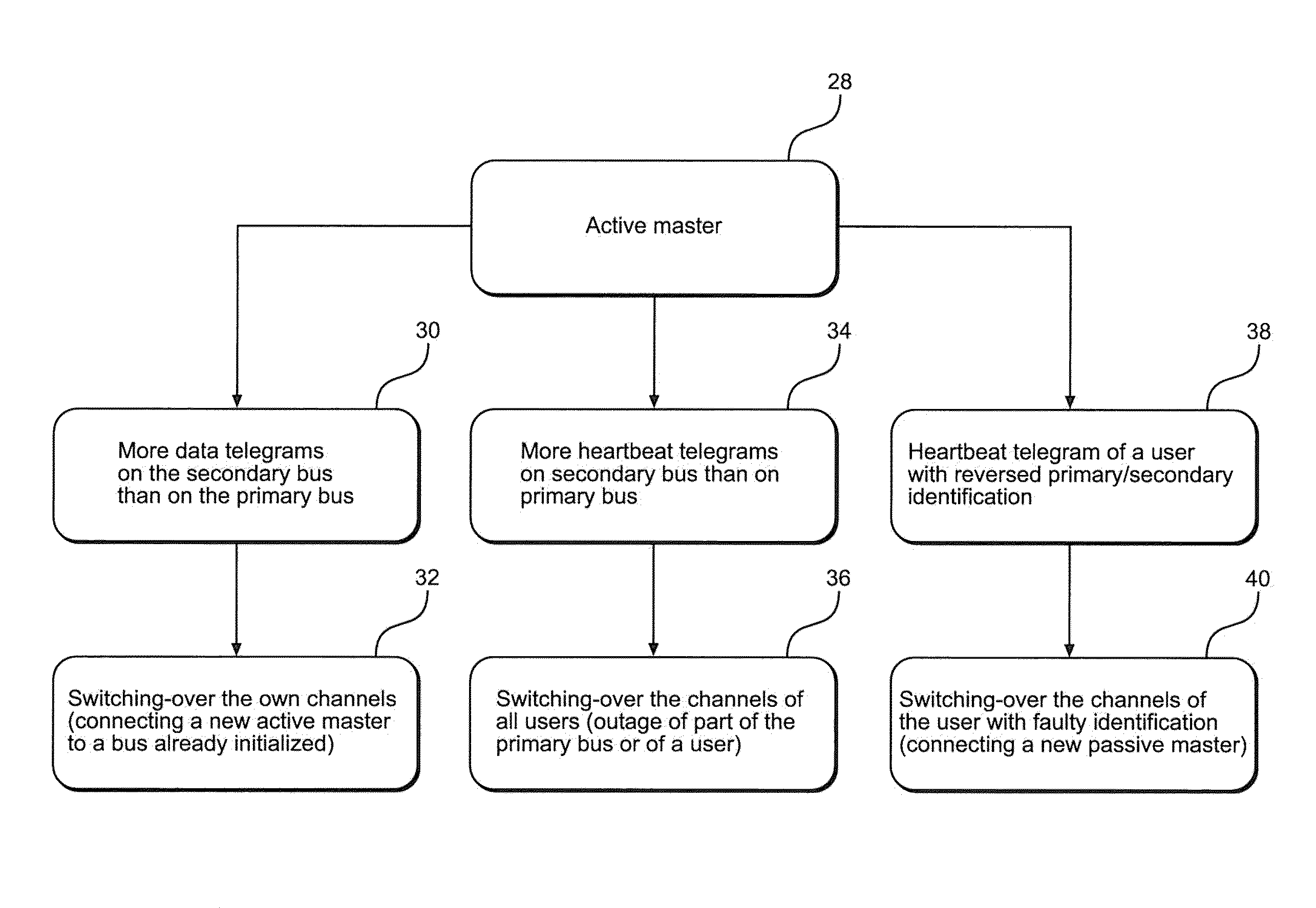
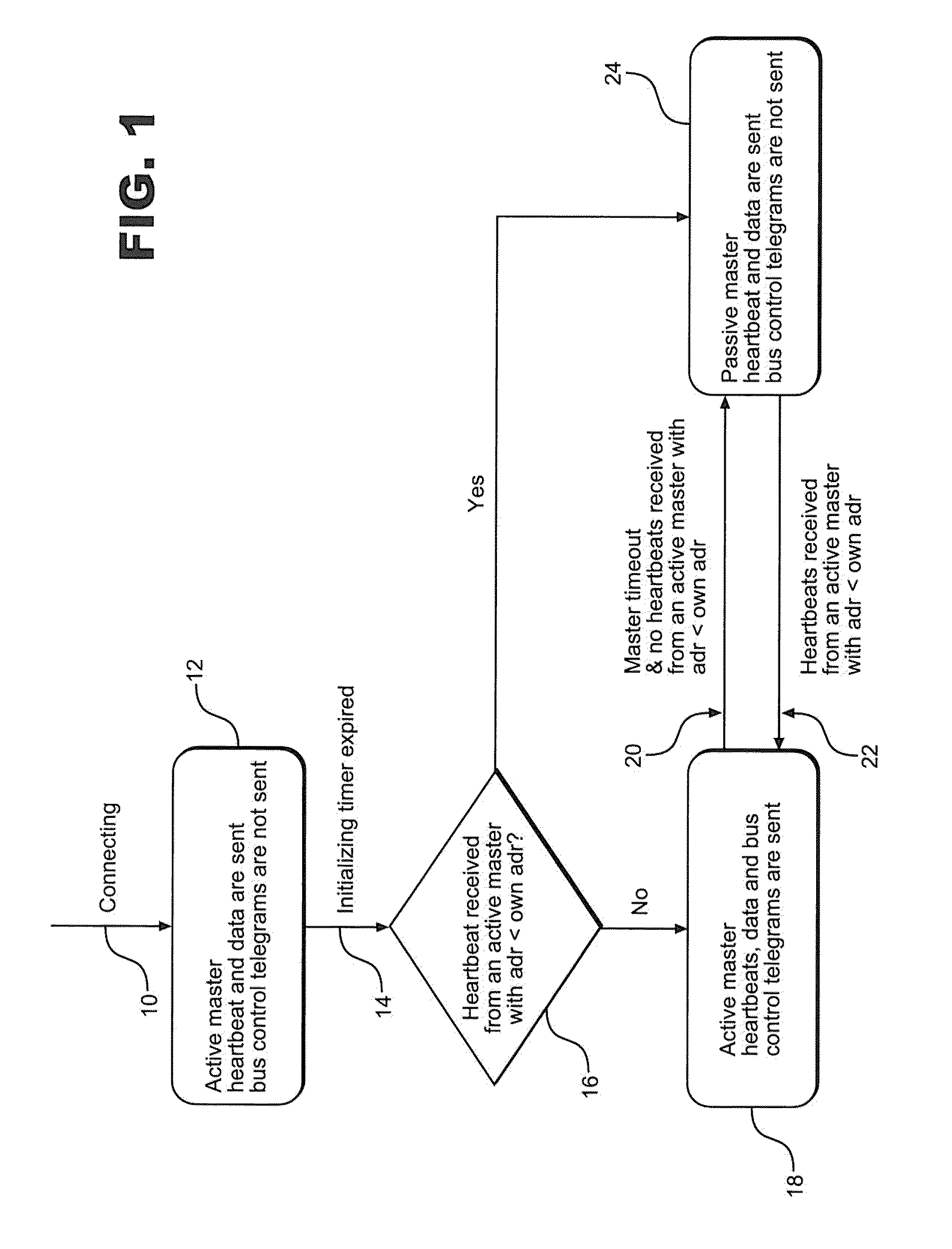
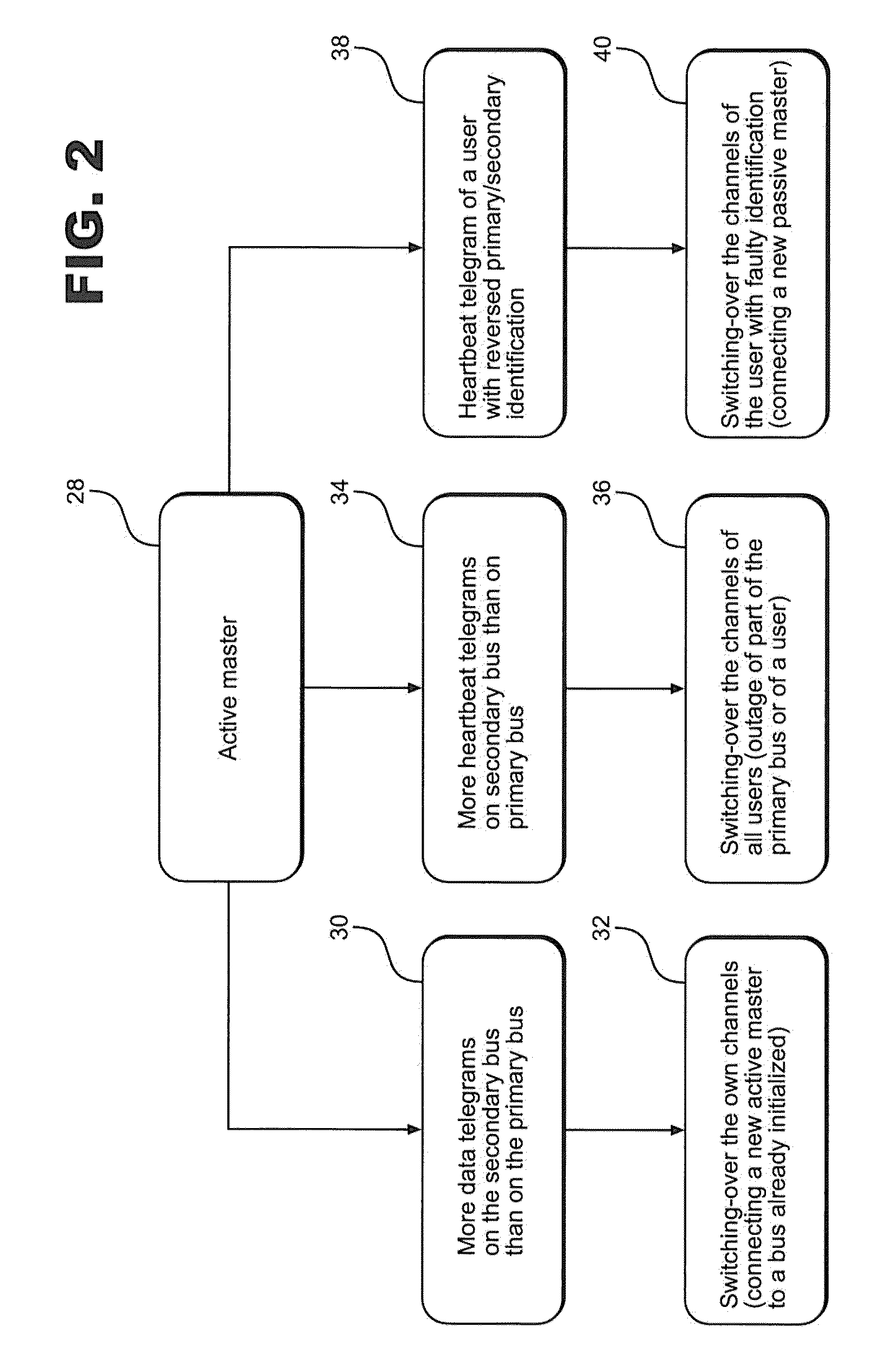
[0019]The bus system that is to ensure the redundancy of the data transmission within a ship rudder control system via a CAN bus, will thus exhibit in each case two identical bus interfaces. According to the state of the system, one user assumes the monitoring function, that is to say, the monitoring function is not firmly coupled to one user. The two bus channels have a fixed designation on each connected node: the so-called channel number Channel 1, Channel 2.

[0020]These channel numbers are assigned in the software (or by configuration in a service mode (in no case in the user mode), one hardware interface receiving the designation Channel A, and the other is Channel B. The choice, which two hardware interfaces are interconnected, is free. It is possible to set up several instances of the Advanced Redundancy Dual Bus within software. Both channels have a defined channel status: Primary Channel or Secondary Channel. These two items of status information are also transmitted in a he...


PUM


Abstract

Ship rudder control, so-called autopilot, includes a multiplicity of components connected with a bus interface to a CAN bus and via this also to each other. A further bus interface on each component of the control system is coupled to a separate, second bus, with the components being provided with unambiguous addresses and further information being assigned that mark the components as monitorable or non-monitorable. A device for emitting telegrams of component addresses and monitorability. A first comparator on all monitorable components start or switch off their own property as a monitoring component using the addresses of other components in received telegrams by comparison, and a second comparator on all monitorable components that use the number of received telegrams by comparison with the number of telegrams received on the other channel causing a change of the channel to that with the higher number of received telegrams under certain circumstances.

Description

BACKGROUND OF THE INVENTION[0001]The invention relates to a ship rudder control, a so-called autopilot, having a plurality of electronic components that are connected to each other by means of a CAN bus. Due to the enormous importance that the correct rudder position and also its indication to a skipper possesses, there are several copies of sensors, position encoders, and display instruments on all ships.[0002]When using electronic components with a CAN bus, as is customary in automotive engineering, there is the problem that outages of single components are often due to poor functional capability of a bus interface or the cabling or the plug connection of the electronic component to the bus. The effects of such fault events are to be minimized as far as possible.[0003]The bus can further be damaged in its property as data line, it being possible for this damage even to be the reception of an unwanted signal, that is to say this damage may be present only temporarily. So as to avoi...

Claims


Application Information

Patent Timeline
IPC IPC(8): G06F13/20
CPCH04L12/40182H04L12/40013
Inventor ROSEN, WOLFGANGPEDERSEN, NORBERTWESSEL, MICHAEL
Owner RAYTHEON ANSCHIITZ GMBH
Why Eureka
Try Eureka