Solid Fuel Boiler Assembly

a boiler assembly and solid fuel technology, applied in the direction of combustion process, fire-tube steam boiler, fire-box steam boiler, etc., can solve the problem that none of the prior art configurations however are suitable for providing heat, and achieve the effect of convenient separation and replacement and low cos

Inactive Publication Date: 2010-04-08
HOFER NEIL +1
View PDF8 Cites 12 Cited by
  • Summary
  • Abstract
  • Description
  • Claims
  • Application Information

AI Technical Summary

Benefits of technology

[0016]the primary and secondary air controls each being operable between an open position arranged to communicate combustion air through the respective combustion air passage and a closed position in which the respective combustion air passage is fully sealed and air flow to the combustions chambers is prevented.
[0017]By providing a boiler assembly including both first and second combustion chambers with respective air controls operable between an open position and a fully sealed closed position, the combustion chambers can be fully sealed for accurately halting combustion until heat is required. Accordingly the fuel in the boiler is combusted in the most efficient manner only as required without wasting heat. In the preferred embodiment, suitable high temperature sealing material is used to optimally seal the air controls in the closed position in which the sealing member is protected on an exterior side of the seating surface against which the sealing material is seated. Similarly any linkage or operating components for opening and closing the air controls is protected at an exterior side of the seating surface about the air passage controlled by the air controls.
[0018]Furthermore in the preferred embodiment, all of the components related to the actuation and control of the air controls and the blowers which deliver the air being controlled to the first and second combustion chambers, are mounted in a modular fashion so as to be readily separated and replaceable within a control housing which is mounted externally from the housing of the boiler assembly locating the combustion chambers and the boiler chamber therein. In the preferred embodiment, communication between each blower and the respective combustion chamber is controlled by both a hinged gate and a slidable damper which can be set independently of one another at various positions between respective open and closed positions to readily control both the volume of air communicated through the respective combustion air passages as well as readily controlling opening and closing of the air passages with the operating components being protected in the optimal manner from creosote and other residuals from the combustion process within the combustion chambers.
[0019]By further locating communication of the secondary combustion air at one end of an elongate secondary combustion chamber which in turn communicates with the primary combustion chamber at a central location therein, it ensures that the secondary combustion air is introduced at a location which is prevented from reaching the high temperatures of the combustion area by the incoming lower temperature combustion air. Accordingly a perforated diffuser member formed of metal may be placed at the location of secondary combustion air introduction into the secondary combustion chamber to optimize mixing of the secondary combustion air into the exhaust from the primary combustion chamber entering the secondary combustion chamber. Furthermore, because the diffuser is kept from becoming too hot by relatively cool incoming secondary air, the diffuser member can be made of low cost metals that do not require any costly alloys or coating to protect the diffuser member from the high temperatures normally encountered at the introduction of secondary combustion air into the secondary combustion chamber.

Problems solved by technology

None of the prior art configurations however are suited for providing heat only during requested intervals while being arranged to be fully shutdown quickly when no heat is desired for maximum efficiency.

Method used


Image

  • Solid Fuel Boiler Assembly
  • Solid Fuel Boiler Assembly
  • Solid Fuel Boiler Assembly

Examples


Embodiment Construction

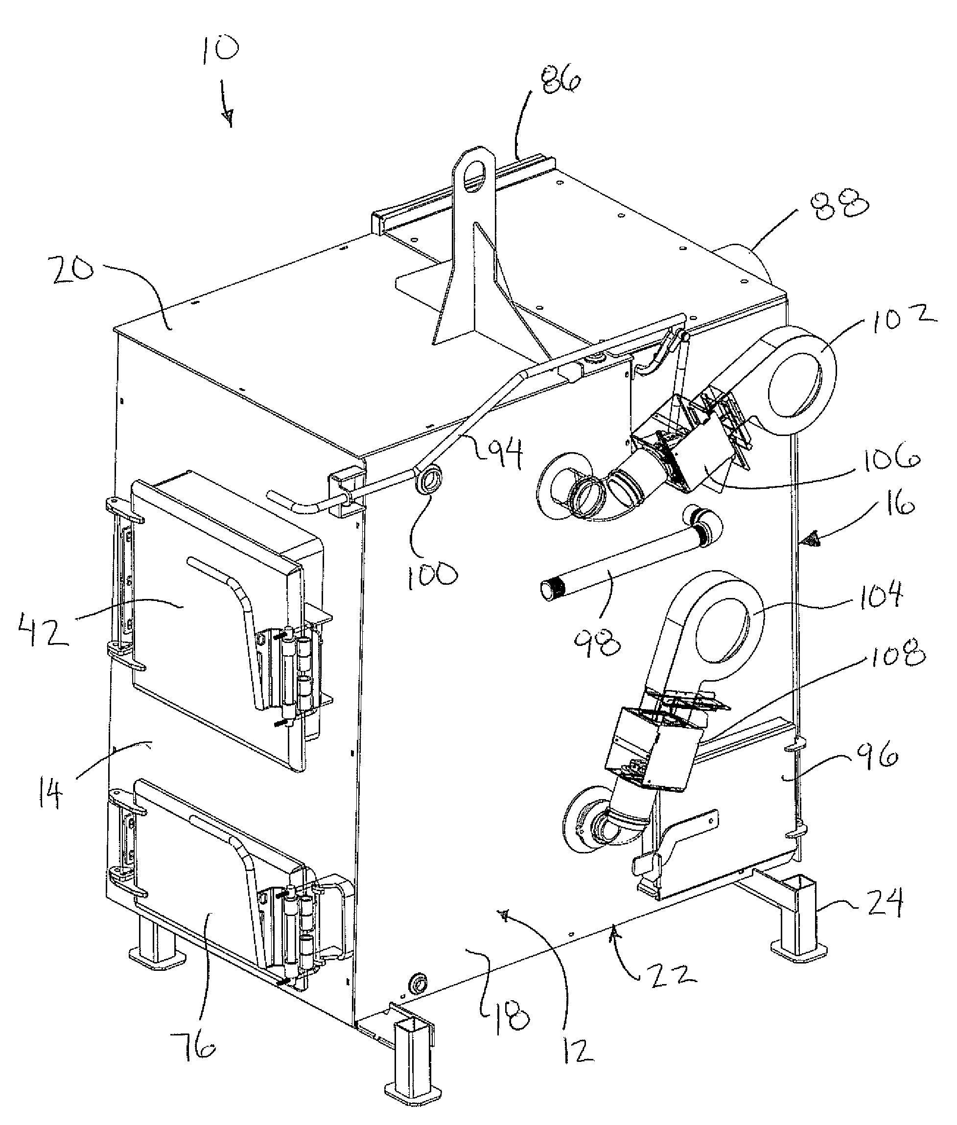
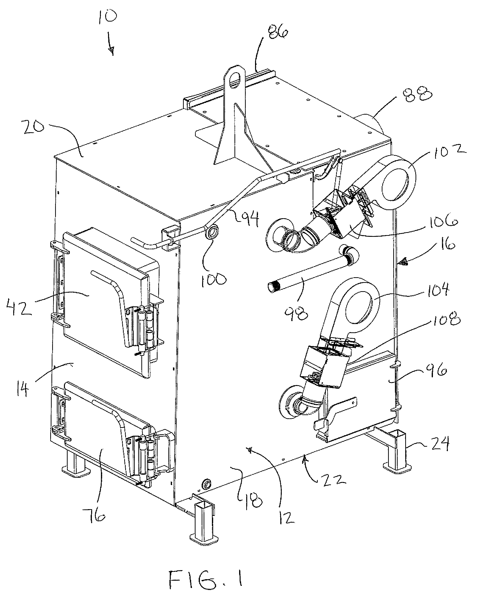
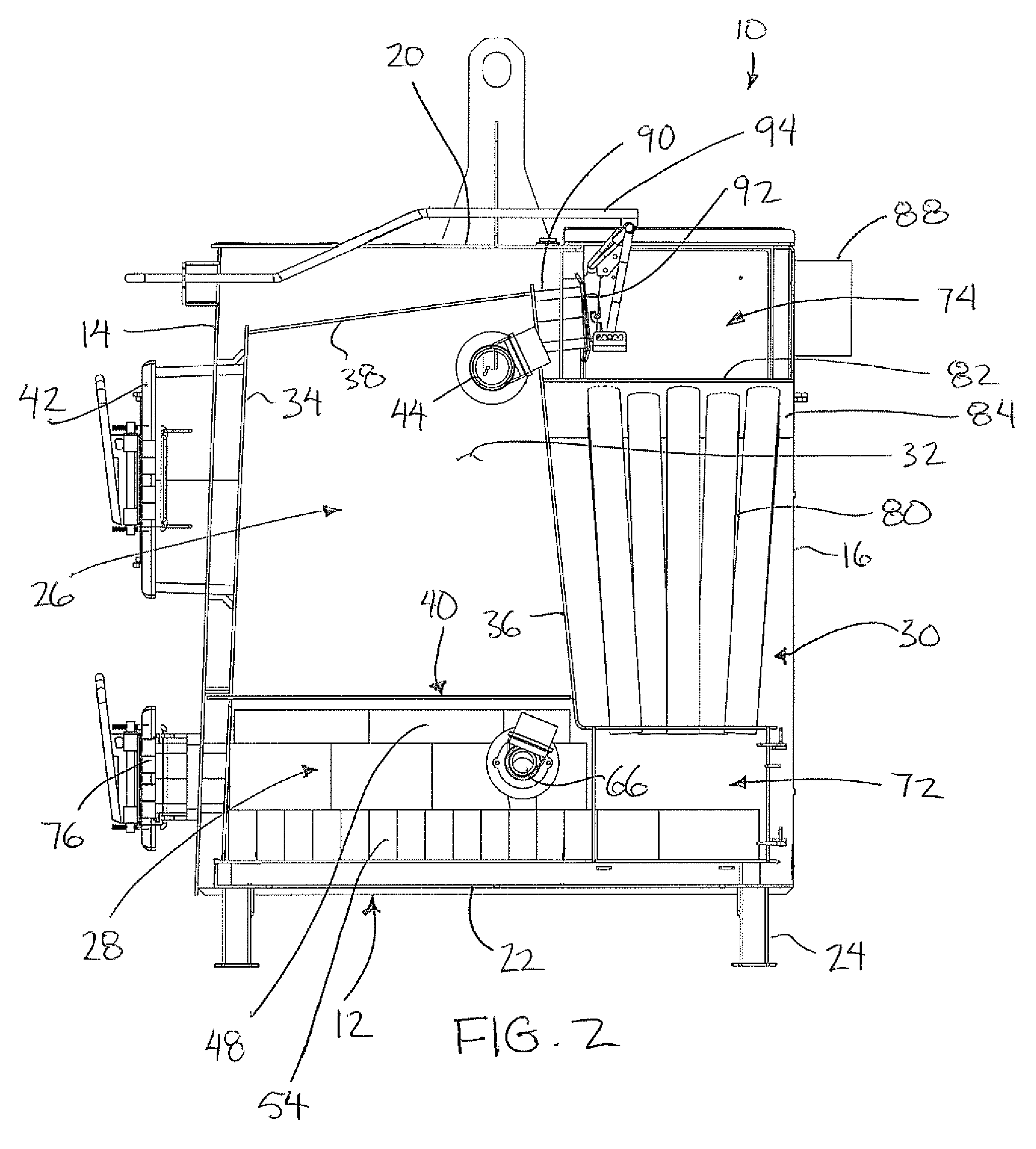
[0077]Referring to the accompanying figures there is illustrated a solid fuel down draft combustion boiler assembly generally indicated by reference numeral 10. The boiler assembly 10 is particularly suited for combusting a solid fuel, for example wood in a two stage combustion in which primary and secondary combustion air is provided in a controlled manner for efficient on demand combustion of the fuel being consumed to maintain the fluid being heated at an optimal set point temperature. The boiler is also well suited for use as an outdoor wood boiler in which a main housing 12 of the boiler can be insulated and appropriately clad to be set up as a stand alone unit outdoors.

[0078]The main housing 12 of the boiler has a front wall 14, a rear wall 16 and two side walls 18 spanning in an upright orientation from the front wall to the rear wall. The main housing further comprises a top wall 20 enclosing the top end of the main housing and a bottom wall 22 enclosing the bottom side of t...


PUM


Abstract

A boiler assembly including primary and secondary combustion chambers includes primary and secondary air controls for controlling combustion air to the chambers respectively. The air controls are operable between open positions to allow combustion in the chambers and a closed position in which the combustion air passages are fully sealed to fully interrupt combustion responsive to heating demands. The air controls are supported externally on the main housing of the boiler assembly so as to be modular and readily releasable from the main housing and the respective combustion air passages. The primary combustion chamber communicates with the secondary combustion chamber at a location partway in between introduction of the secondary combustion air and the exhaust passage.

Description

FIELD OF THE INVENTION[0001]The present invention relates to a solid fuel downdraft combustion boiler assembly including a primary combustion chamber and a secondary combustion chamber, each arranged to receive a controlled amount of combustion air.BACKGROUND[0002]Various designs of boilers are known in the prior art in which fuel is consumed for heating a fluid which is in turn used to transfer heat to a target area to be heated. Prior art examples are described in U.S. Pat. No. 6,718,819 by Brazier et al, U.S. Pat. No. 4,479,481 by Ingersoll et al., and U.S. Pat. No. 1,501,847 by Howell and European patent application 0 084 852 by Giovanni. None of the prior art configurations however are suited for providing heat only during requested intervals while being arranged to be fully shutdown quickly when no heat is desired for maximum efficiency.SUMMARY OF THE INVENTION[0003]According to one aspect of the invention there is provided a boiler assembly comprising:[0004]a primary combusti...

Claims


Application Information

Patent Timeline
Patent Type & Authority Applications(United States)
IPC IPC(8): F23C6/00F22B35/08F23L13/00F23N3/00
CPCF22B9/16F22B13/02F23B10/00F23L9/02F23L1/00F23L3/00F23L5/02F23B60/00
Inventor HOFER, NEILWOLLMANN, RAY
Owner HOFER NEIL
Why Eureka
Try Eureka