
Electric compressor

a compressor and electric technology, applied in the direction of positive displacement liquid engine, piston pump, magnetic circuit shape/form/construction, etc., can solve the problems of motor case deformation and stator insertion failure, and achieve the effect of preventing the occurrence of insertion failur

Active Publication Date: 2010-04-08
MITSUBISHI HEAVY IND LTD
View PDF10 Cites 12 Cited by
  • Summary
  • Abstract
  • Description
  • Claims
  • Application Information

AI Technical Summary

Benefits of technology

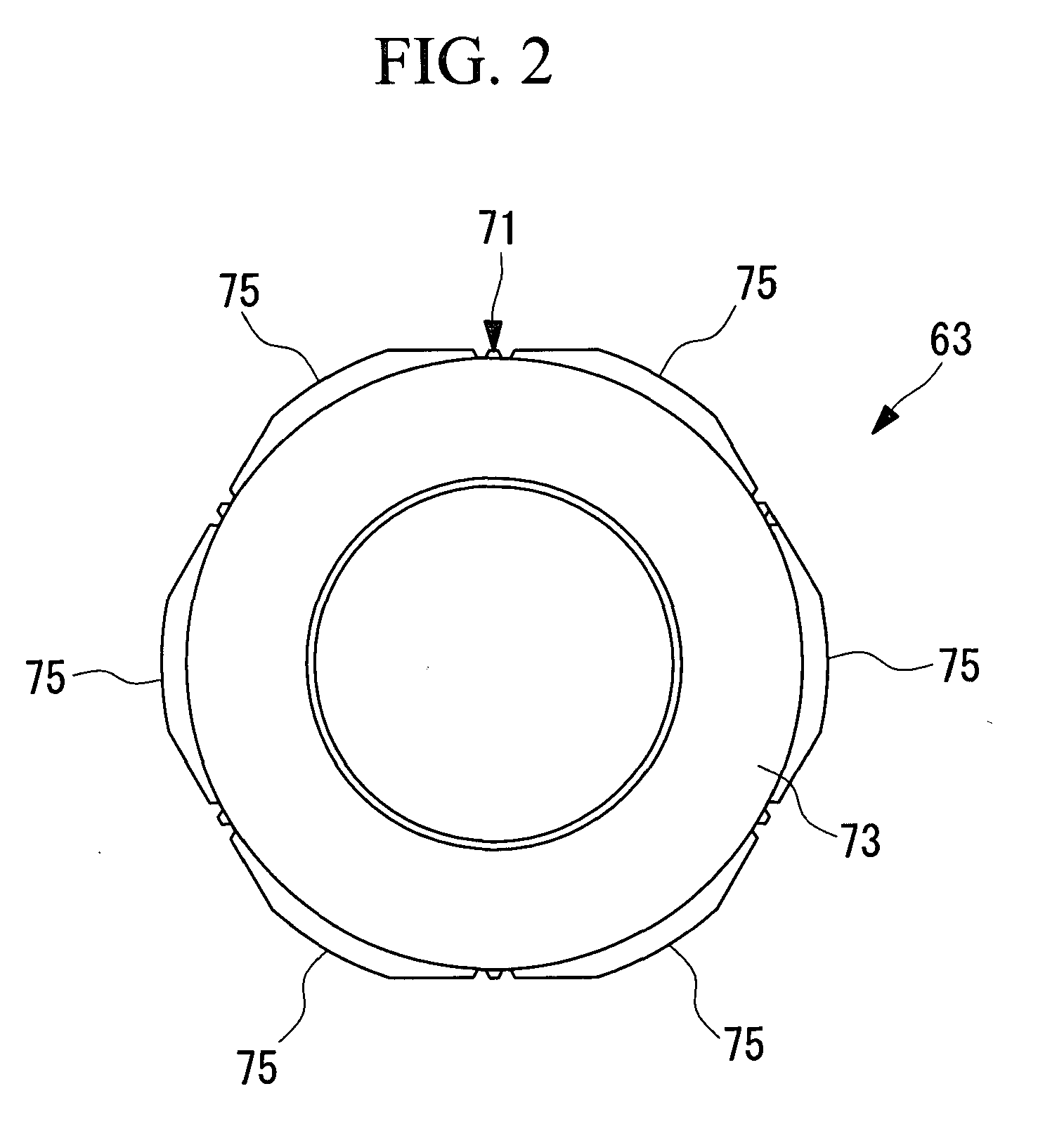
[0007]To improve productivity and reduce production costs, the above-described motor case is produced by forming a motor case material having a rough shape by casting (for example, die casting), followed by machining or the like only portions that require dimensional accuracy. For example, the surface (hereinafter, referred to as a shrink-fitting surface), in contact with the above-descried stator, of the inner peripheral surface of the motor case is machined in a cylindrical shape because dimensional accuracy is required. On the other hand, the other areas of the above-described inner peripheral surface that do not require dimensional accuracy are often kept as is in the form of the motor case material surface (a surface after casting, hereinafter, referred to as a mill-scale surface).

Problems solved by technology

For fixing by shrink fitting, the problems of deformation of the motor case and stator insertion failures have been noted.

Method used


Image

  • Electric compressor
  • Electric compressor
  • Electric compressor

Examples


Embodiment Construction

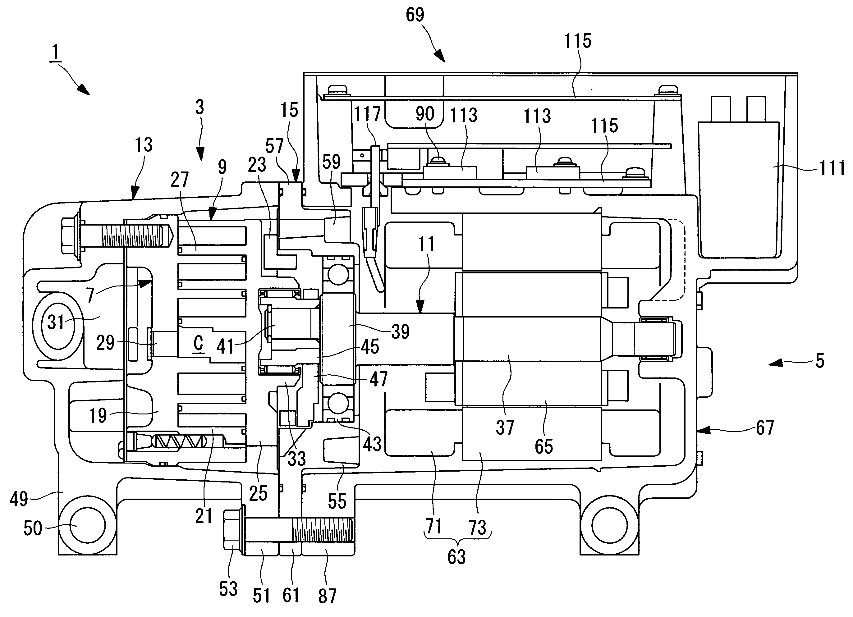
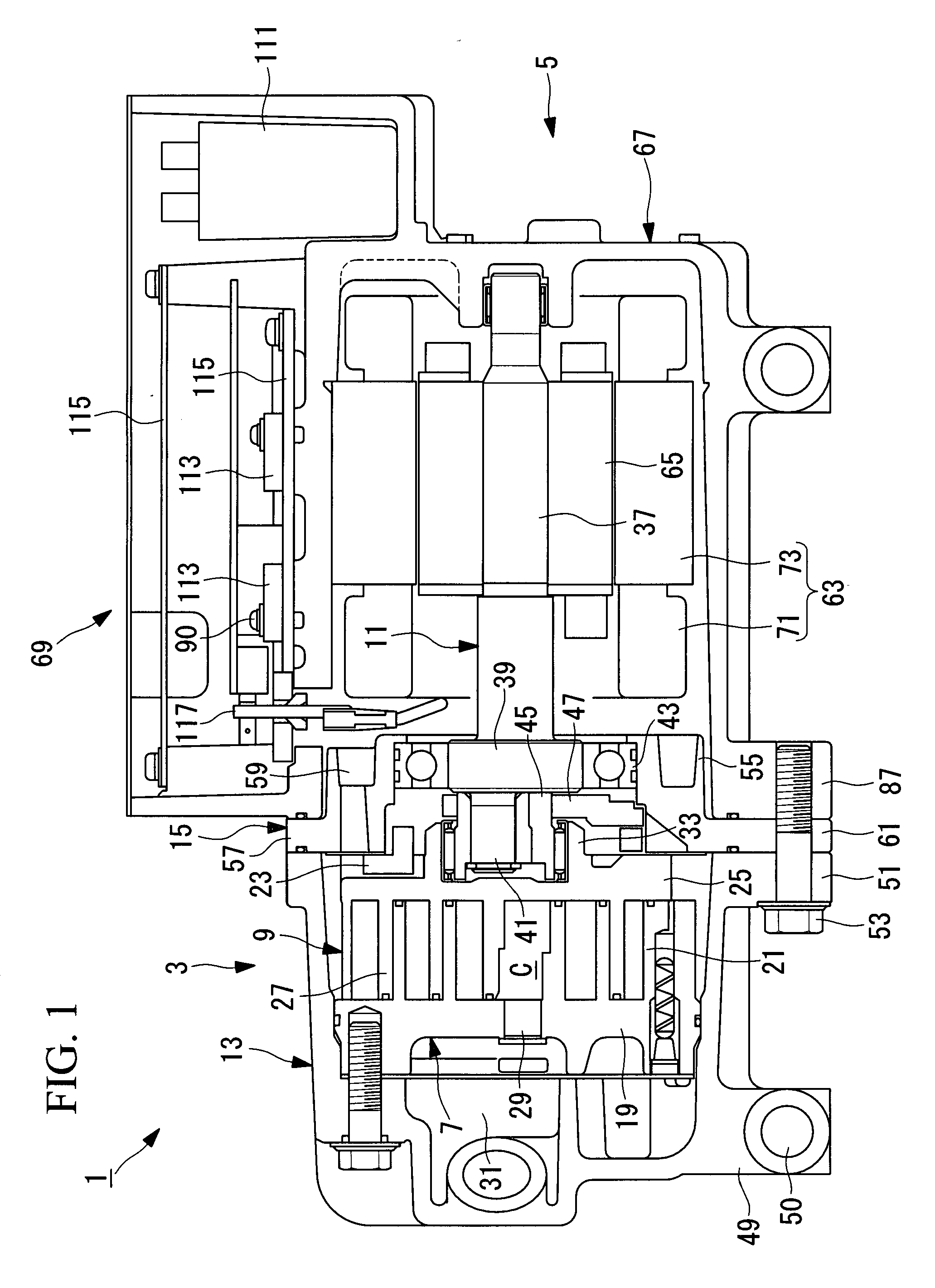
[0058]An electric compressor according to an embodiment of the present invention will be described with reference to FIGS. 1 to 8.

[0059]FIG. 1 is a sectional view describing in outline the configuration of an electric compressor according to an embodiment of the present invention.

[0060]In this embodiment, an electric compressor 1 is described when applied to a compressor for use in a vehicle air conditioner, which is an electric compressor in which the driving speed is controlled by an inverter.

[0061]As shown in FIG. 1, the electric compressor 1 is provided with a scroll compressing unit (compressing unit) 3 for compressing refrigerant (fluid) used in a vehicle air conditioner and a motor unit 5 for driving the scroll compressing unit 3.

[0062]The scroll compressing unit 3 is provided with a fixed scroll 7 and a rotary scroll 9 for compressing refrigerant, a main shaft 11 that transfers the rotational driving force of the motor unit 5 to the rotary scroll 9, a first housing 13 that a...


PUM


Abstract

To provide an electric compressor in which the occurrence of shrink-fitting failures can be prevented when a stator is shrink-fitted in a motor case. Provided are a casing (67) in which the inner circumferential surface of the cylinder is provided with a first inner circumference (101) and a second inner circumference (103) whose radius is larger than the first inner circumference (101), the inner circumference (101) having an inclination that becomes more distant from a central axis (C) from a bottom face (79) toward an opening (85); a compressing unit that compresses fluid; and a rotor and a stator that rotationally drive the compressing unit, wherein the first inner circumference (101) and the second inner circumference (103) are provided with a substantially cylindrical insertion surface (105) whose radius is larger than the second inner circumference (103) and in which the stator is inserted; and at least the first inner circumference (101) is provided with an enlarged diameter portion (109) whose radius is larger than the insertion surface (105) and which makes the distance from the end at the opening (85) side of the insertion surface (105) to the opening (85) substantially equal.

Description

TECHNICAL FIELD [0001]The present invention relates to electric compressors, and in particular, to an electric compressor in which a stator of a motor unit is shrink-fitted in a motor case of the electric compressor.BACKGROUND ART[0002]A known electric compressor in the related art is provided with a compressing unit that compresses fluid and a motor unit that drives the compressing unit. The motor unit is provided with a rotor and a stator that generate a rotating force to be transferred to the compressing unit. The rotor is connected to the compressing unit, and the stator is fixed to the motor case of the electric compressor.[0003]Known methods for fixing the stator to the motor case are press fitting, shrink fitting, and welding. Among these fixing methods, shrink fitting is a method which allows easy insertion of the stator into the motor case by heating the motor case to thermally expand it and fixing the stator in the motor case more firmly due to shrinkage of the motor case ...

Claims


Application Information

Patent Timeline
IPC IPC(8): H02K5/04H02K5/22H02K5/00
CPCF01C21/10F04B35/04F04C18/0215F04C29/0085H02K15/02F04C2240/30H02K1/187H02K5/06F04C2230/60
Inventor ISHIKAWA, MASAYUKIHAGITA, TAKAYUKIHIRANO, TAKESHIWATANABE, TAKAYUKIMURABAYASHI, HISASHI
Owner MITSUBISHI HEAVY IND LTD
Learn More