Diffractive device

a display device and diffractive technology, applied in the field of refractive image display devices, can solve the problems of reducing efficiency, inherently low diffraction efficiency, and not recognizing or addressing

Inactive Publication Date: 2010-04-08
OPTAGLIO
View PDF35 Cites 62 Cited by
  • Summary
  • Abstract
  • Description
  • Claims
  • Application Information

AI Technical Summary

Benefits of technology

[0011]According to one aspect of the present invention there is provided a display device viewable by reflection and comprising an image providing display element including a spatial light modulator providing an image viewable by the transmission of light therethrough and backed by an achromatic diffractive reflector comprising a reflective surface relief structure, characterized in that upon off-axis illumination of the display device by ambient white light, the achromatic surface relief structure reflects diffuse light into a defined viewing zone substantially normal to the device for viewing by an observer, and said diffuse reflective reflection being achromatic and comprising a plurality of small non-overlapping areas of individual diffractive devices each of a size below the normal resolution of the human eye and whose superposition of diffractive effects provides an achromatic diffuse reflection into a defined viewing zone for enhanced observation of the image providing display.

Problems solved by technology

However, the work does not recognise or address the issue of the usually sub-optimal reflected light intensity and diffraction efficiency of this type of element in that the full aperture embossed hologram suggested will inherently have low diffraction efficiency.
This will be because of the multitude of superimposed spatial frequencies it contains in order to give a white appearance which reduce the efficiency of the structure due to fringe competition and also because the embossed holographic or diffractive elements envisaged are relatively simple surface relief diffractive devices and will therefore diffract equally into two diffracted orders, both +1 and −1, (and often more) thus effectively wasting up half of the light diffracted by the embossed hologram which fails to go into the desired diffractive order to be seen by the viewer.
The problem with using volume holographic elements is that volume elements have generally a narrow selection of replay angles and wavelengths over which they are efficient and generally use higher cost materials than alternative structures and normally have a narrow angular and spectral response, thus limiting the display brightness by limiting the usable input light, having a higher cost base, and sometimes material stability issues.
Known work also uses achromatic effects formed from 3 volume holographic structures overlapping within the same medium, which will reduce the diffraction efficiency attainable.
These diffractive, optically variable image forming devices are used as anti-counterfeit devices both because their effects are highly recognisable and cannot be duplicated by print technologies, and because specific and difficult to replicate optical and engineering techniques are required for their production.
There are two problems with this approach, firstly that although the reflectivity remains relatively high, the transmissivity is essentially much lower than would be preferred, driving up the back-light power requirements which is a negative aspect for mobile display applications such as telecommunications where energy balance is important.
Secondly, although it would be preferable to use a more transmissive device, as the thickness of the aluminium film is reduced to increase transmission the film becomes very absorbing so reducing both the reflectivity and transmissivity by absorption, making the system lossy.
Thin metal layers, particularly aluminium are also prone to oxidation becoming grey in colour.
Thus it is not really practical to obtain efficient higher transmissions than say 15% using aluminium without degrading significantly both reflection and transmission by absorption.
Similar, but typically worse, characteristics apply to all such metals used as thin films, where the reflectivity / transmissivity balance is severely degraded by absorption.
Although this approach provides a useful extra graphical element to the display and also allows a higher transmission of the transflector without having absorption issues, the basic relatively low transmission of the transmissive part of the device remains in place, so requiring a more powerful back light element with greater power consumption than would otherwise be needed.
Again this process cannot overcome the issue of relatively low transmission of the transflector for reasonable reflection.

Method used


Image

  • Diffractive device
  • Diffractive device
  • Diffractive device

Examples


Embodiment Construction

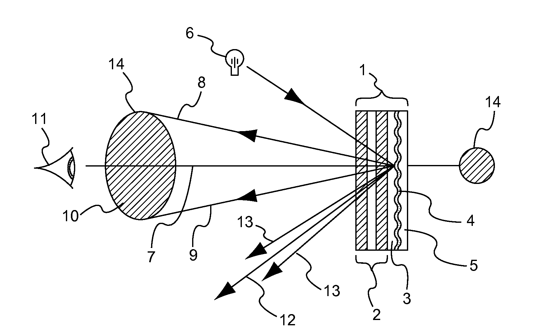
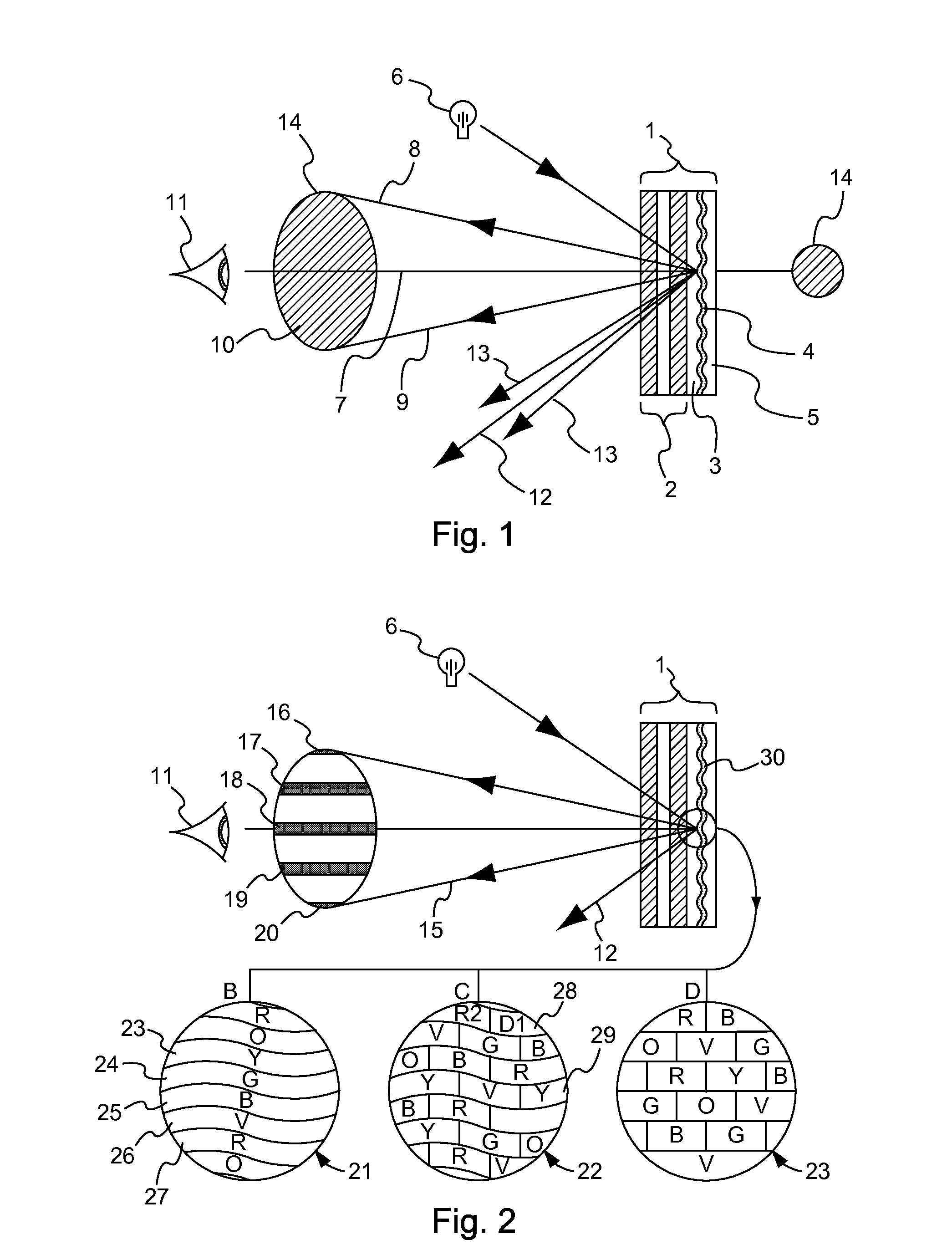
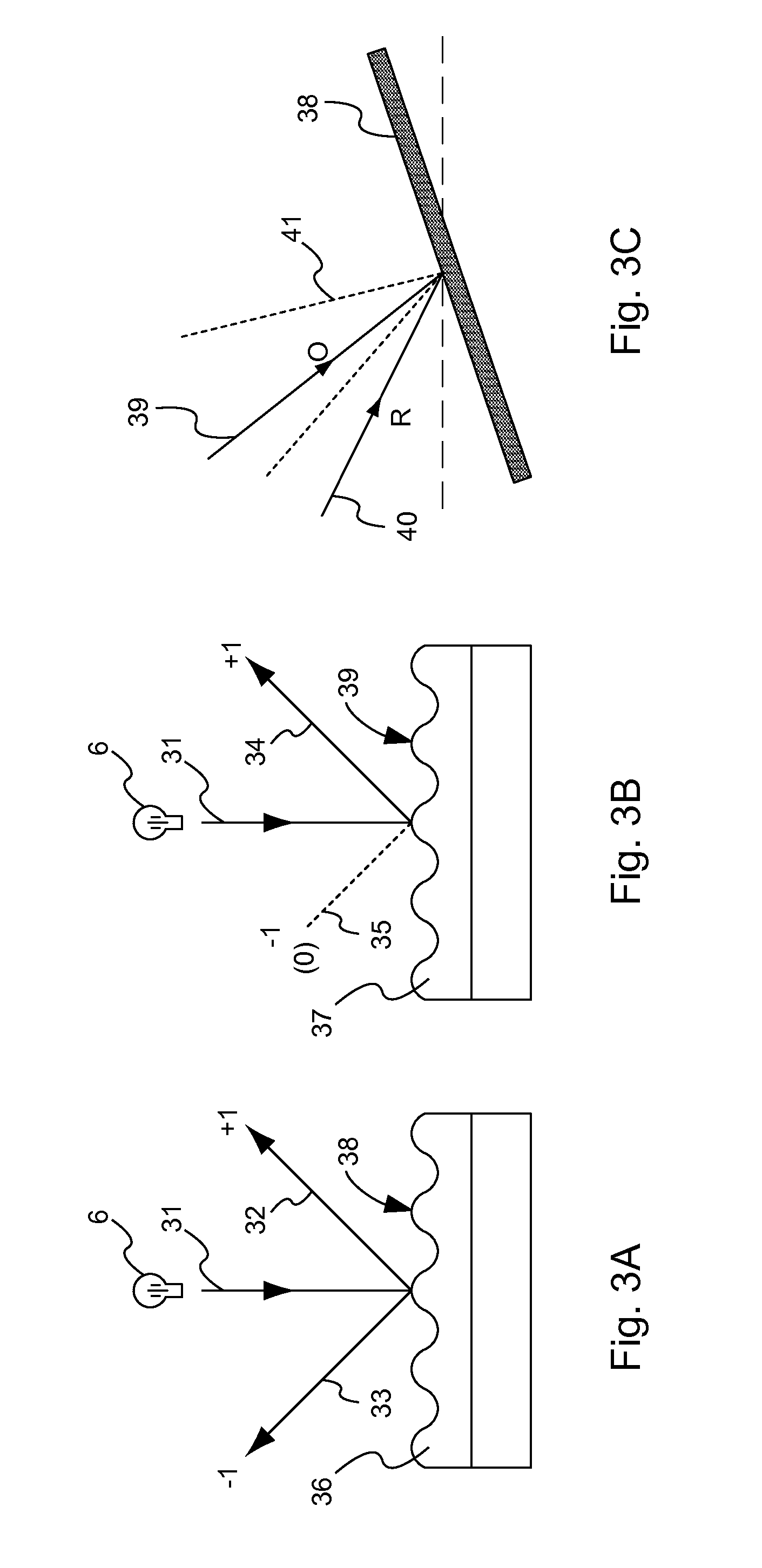
[0105]Sections 1 and 2: Here, new types of enhanced higher efficiency and otherwise improved holographic and diffractive devices for use typically as reflective holographic enhancement film are proposed, particularly for display applications, and characterised as achromatic diffractive device, made up of many non overlapping individual elements of a size beneath the normal eye resolution the sum of whose diffracted images creates the achromaticity of the device. Such devices can also have non classical diffractive replay (blazed), providing an enhanced reflectivity in the desired diffracted order. These new devices are holographically (Section 1) generated or directly written by electron beam lithography, (Section 2) for use as optical enhancement elements for image providing display elements such as liquid crystal displays to enhance the brightness and visibility of such displays when viewed in reflection ambient lighting conditions. Also disclosed is the creation of new features o...


PUM


Abstract

The invention provides in particular for an achromatic diffractive diffuser comprising a surface relief diffractive device arranged such that, under illumination by ambient light, the diffractive effect serves to provide a uniform achromatic diffuser reflection into a defined viewing zone for observation by an observer, and also such that the achromatic diffractive replay of the device has a non-symmetric distribution of diffractive light intensity between positive and negative diffractive order such that the diffractive efficiency in the desired diffractive order is enhanced over that of the undesired order to provide an enhanced brightness achromatic device.

Description

BACKGROUND[0001]This invention relates to the field of reflective image display devices designed to be viewed under reflected ambient lighting. The invention reveals specifically new novel achromatic diffractive optical elements and some new associated structures and features and novel manufacturing techniques for the same. These can be used to enhance the visibility of reflectively viewed display devices by the use of diffractive element, particularly to enhance the brightness of LCDs and similar displays.[0002]Such reflective display devices include image providing display devices, such as liquid crystal display elements or other similar such devices. For the case of a transmissive type liquid crystal display, such devices are usually made viewable in reflection by backing them with a diffusing element. Typically this will be specular diffuser, although it is known to use holographic diffusers formed from reflection holograms or reflector backed transmission holograms, or reflecti...

Claims


Application Information

Patent Timeline
Patent Type & Authority Applications(United States)
IPC IPC(8): G02B5/02G02B5/18
CPCF21V33/006G02B5/0215G02B5/0252G02B5/0268G02B5/0284G02B5/0289B42D25/328G02B5/1861G02B6/0038G02B6/0051G02B6/0061G02F1/133504G02B5/0294G03H1/0244G03H1/08G03H1/182G03H1/265G03H2001/0478G03H2001/184G03H2001/188G03H2001/2265G03H2001/2268G03H2001/303G03H2250/36
Inventor DRINKWATER, K. JOHN
Owner OPTAGLIO
Why Eureka
Try Eureka