Integrated microfluidic device with reduced peak power consumption

a microfluidic device and integrated technology, applied in the field of integrated microfluidic devices, can solve the problems of loss of precision in heating and/or cooling, loss of precision in sensing circuits, etc., and achieve the effects of reducing unwanted voltage drops on supply lines, reducing peak power consumption, and reducing heating precision

Inactive Publication Date: 2010-04-08
KONINKLIJKE PHILIPS ELECTRONICS NV
View PDF11 Cites 29 Cited by
  • Summary
  • Abstract
  • Description
  • Claims
  • Application Information

AI Technical Summary

Benefits of technology

[0016]This can help reduce peak power consumption, and thus reduce unwanted voltage drops on supply lines. These can cause loss of precision in heating and / or cooling and sensing circuits. They are more of a problem for arrays on glass substrates using cheaper manufacturing techniques.

Problems solved by technology

These can cause loss of precision in heating and / or cooling and sensing circuits.
They are more of a problem for arrays on glass substrates using cheaper manufacturing techniques.

Method used


Image

  • Integrated microfluidic device with reduced peak power consumption
  • Integrated microfluidic device with reduced peak power consumption
  • Integrated microfluidic device with reduced peak power consumption

Examples


embodiment 1

[0158]FIGS. 27, 28 Mapping of PCR Cycle Phases within an Array

[0159]FIG. 27 shows the temperature cycling phases of an example PCR, involving a low temperature φ0, a medium temperature φ1 and a higher temperature phase φ2. The maximum power consumption will occur if all chambers in the array experience the same cycle at the same time i.e. cycle φ2, the highest temperature phase. To avoid this the temperature cycling in the array should be arranged so that the minimum number of φ2 temperature phases are occurring at any one time. The sequence shown in FIG. 28 will enable this. This shows a first row starting with phase 0, then going to phase 1, then phase 2, and repeating this. A second row starts with phase 1, then 2, then 0 and repeats. A third row starts with phase 2, then 0, then 1, and repeats. Note that the temperature in each chamber can be different even if the cycle phase is the same i.e. small variations in the temperature are allowed to enable the benefits of multiplexed P...

embodiment 2

[0161]FIG. 29 Phase Shifting of PCR Temperature Cycles

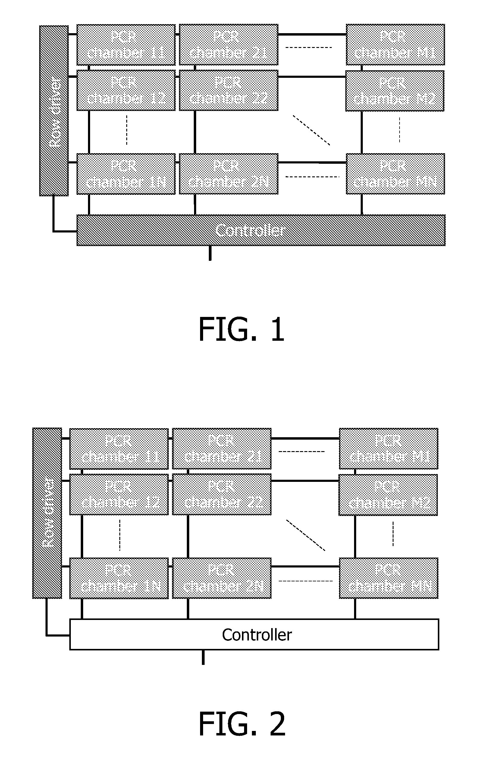
[0162]Maximum electrical power consumption will occur when the temperature is required to rise, as the controller realizes it must change to a higher temperature maximum power in consumed until the target temperature is approached. Therefore by offsetting the phases of the PCR cycles of each chamber, again the peak power is reduced. FIG. 29 illustrates the procedure. The phase offset can be optimized to achieve the lowest peak power consumption for a given configuration of PCR chambers. If there is a row or column of chambers connected to the same power supply line then it is desirable to protect that line from large voltage drops that may occur with high peak powers. Then the chambers in that column or row should be offset in phase as shown in FIG. 29.

[0163]If the number of chambers within one row or column is N then the period of one temperature phase is divided by N and this will represent the phase shift required to avoid ris...

embodiment 3

[0164]FIG. 30, Altering PCR Phase Lengths

[0165]The phase lengths can also be altered to a certain degree as long as they do not interfere with the biological processes. FIG. 30 shows possible waveforms of neighboring chambers. The duration of the highest temperature is shortened in one cycle, and lengthened in another cycle. This is arranged so that for a given chamber the average duration over a number of cycles is not changed. For a given point in time, one chamber (top waveform) has a longer high temperature duration. The middle waveform has an unchanged duration and the lower waveform has a shorter duration. Notice how the lengths of the phases φ0, φ1 and φ2 can vary but the period of the temperature cycling remains constant so that all PCR chambers finish at approximately the same time.

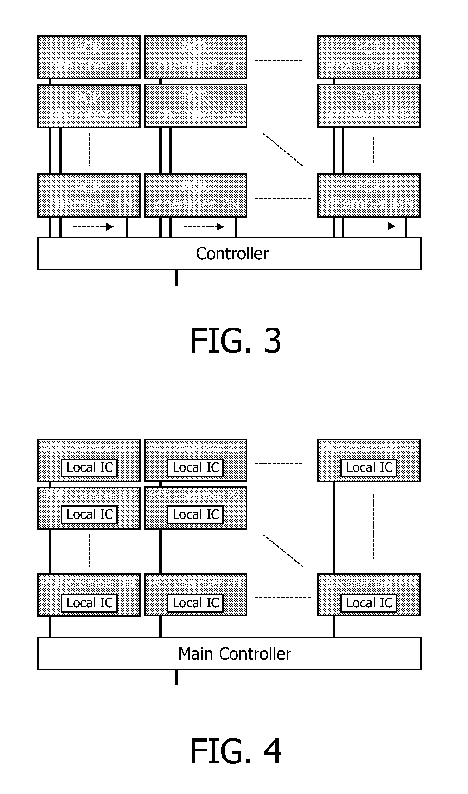
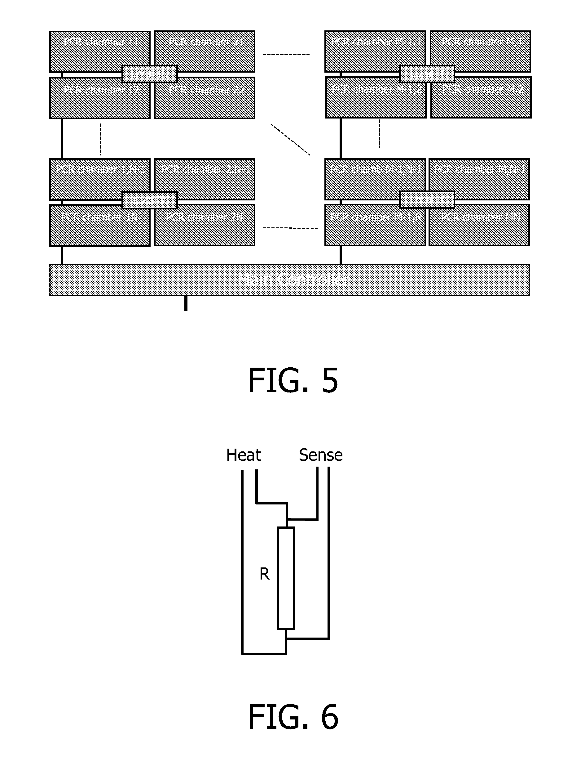
[0166]FIGS. 31-37 Local Heating Control within a PCR Chamber

[0167]One serious issue is that heating from thin film metals on an insulating substrate such as a glass substrate can produce non-unif...


PUM

PropertyMeasurementUnit
gate lengthsaaaaaaaaaa
frequencyaaaaaaaaaa
thermal time constantaaaaaaaaaa

Abstract

An integrated microfluidic device having a number of chambers (11-MN) for heating a fluid, a number of electrical heating elements (R) for heating different ones of the chambers, a controller for controlling the heating elements to vary a temperature of the fluid in the chambers repeatedly through a cycle of different temperatures, the controller being arranged to time the temperature cycle for a given one of the chambers to be out of phase with temperature cycles of others of the chambers. This can help reduce peak power consumption, and thus reduce unwanted voltage drops on supply lines. These can cause loss of precision in heating and sensing circuits. The device can comprise a low temperature polysilicon on a glass substrate. The controller can be coupled to the heating elements using an active matrix of control lines and switches (T2).

Description

FIELD OF THE INVENTION[0001]This invention relates to integrated microfluidic devices having a plurality of chambers on the substrate for handling fluids, a number of electrical heating elements for heating different ones of the chambers, and a controller for controlling the heating elements.BACKGROUND OF THE INVENTION[0002]Micro-fluidic devices are at the heart of most biochip technologies, being used for both the preparation of fluidic samples and their subsequent analysis. The samples may e.g. be blood based. As will be appreciated by those in the art, the sample solution may comprise any number of things, including, but not limited to, bodily fluids like blood, urine, serum, lymph, saliva, anal and vaginal secretions, perspiration and semen of virtually any organism: Mammalian samples are preferred and human samples are particularly preferred; environmental samples (e.g. air, agricultural, water and soil samples); biological warfare agent samples; research samples (i.e. in the c...

Claims


Application Information

Patent Timeline
Patent Type & Authority Applications(United States)
IPC IPC(8): C12M1/38B01J19/00
CPCB01J19/0093B01L2300/1827B01J2219/00828B01J2219/00831B01J2219/00853B01J2219/00869B01J2219/00873B01J2219/00891B01J2219/00961B01J2219/00986B01L3/5027B01L7/52B01L2200/147B01L2300/0819B01J2219/00783
Inventor FISH, DAVID ANDREW
Owner KONINKLIJKE PHILIPS ELECTRONICS NV
Why Eureka
Try Eureka