HPLC preparative column design

a technology of preparative columns and liquid chromatography, which is applied in the direction of ion exchangers, separation processes, instruments, etc., can solve the problems of large preparative columns that can be quite costly, inability to hold operating temperatures within a specific range, and bulky ends, so as to reduce the cost of the column

Inactive Publication Date: 2010-04-15
ZELECHONOK YURY +1
View PDF15 Cites 9 Cited by
  • Summary
  • Abstract
  • Description
  • Claims
  • Application Information

AI Technical Summary

Benefits of technology

[0007]A basic object of this invention is to provide an HPLC preparative column design that is fabricated using less HPLC compatible materials, than a comparable prior art preparative column, so as to reduce the column costs, particularly for large columns.

Problems solved by technology

The larger preparative columns can be quite costly due to both the significant quantity and cost of the HPLC compatible materials needed to make them.
A further problem experienced when using existing preparative columns is the inability to hold the operating temperatures within a specific range.
One reason for this is that the tubular column typically has bulky ends that reduce effective thermal transfer column contact with flat surfaces of conventional heating / cooling apparatus.
Another reason is that the column body is fabricated primarily of HPLC compatible materials having poor thermal conductivity, further reducing effective thermal transfer with the conveyed liquid.

Method used


Image

  • HPLC preparative column design
  • HPLC preparative column design
  • HPLC preparative column design

Examples


Embodiment Construction

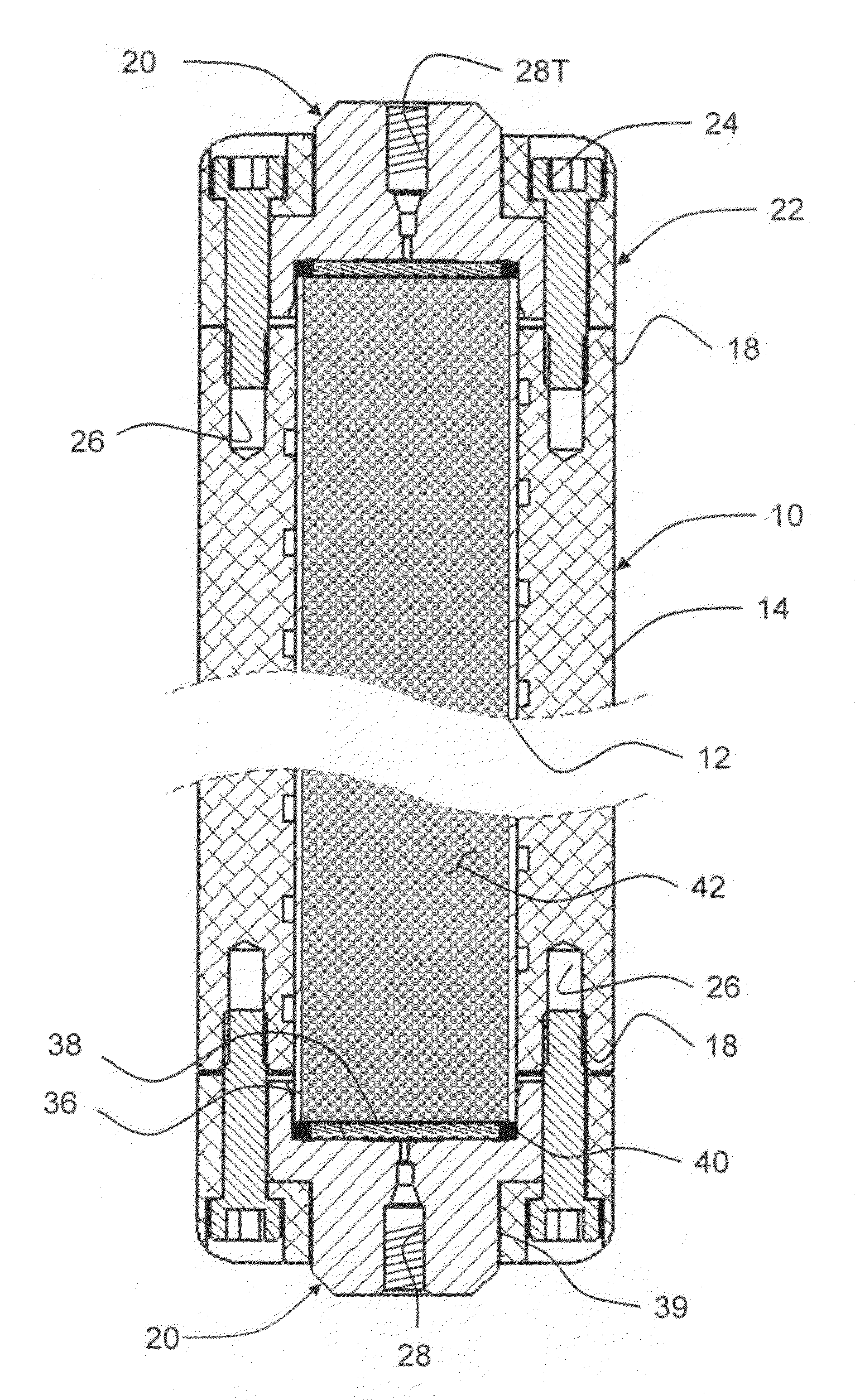
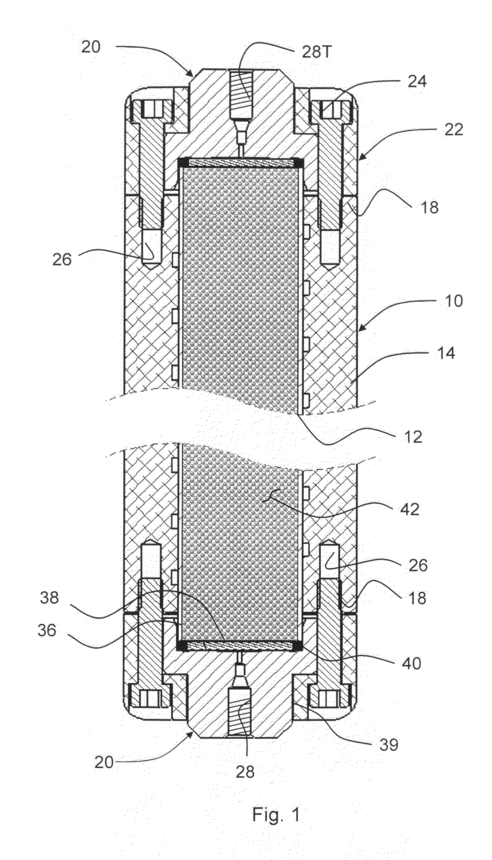
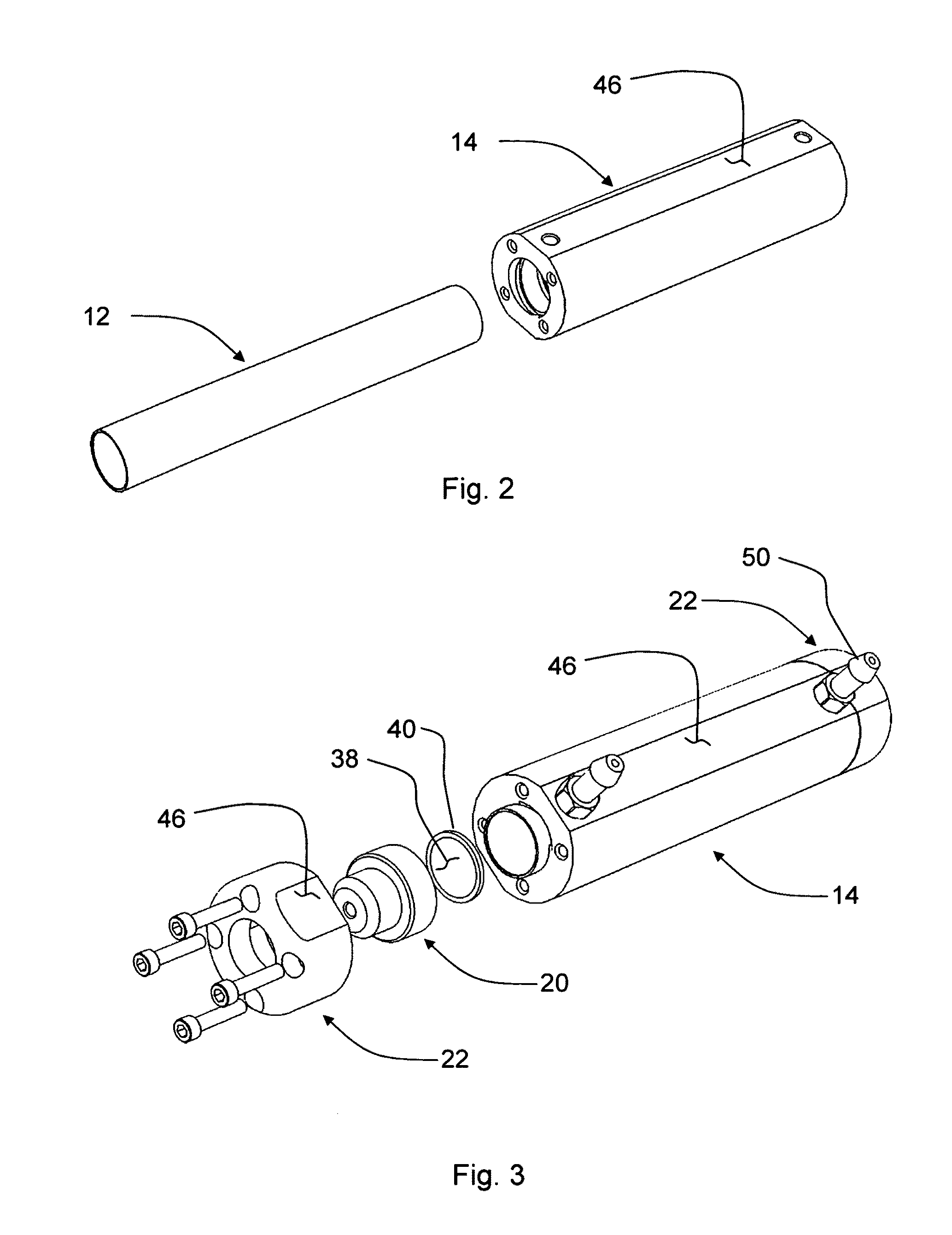
[0015]The inventive HPLC preparative column 10 has an inner thin wall HPLC compatible material tube 12 that is press-fit into an overlying outer tube or sleeve 14 of aluminum. The inner tube 12 might be slightly longer than the outer sleeve 14, by possibly ¼″ or so, so that its ends 16 protrude slightly (and generally equally) beyond the adjacent end faces 18 of the outer sleeve 14.

[0016]Annular end fittings 20 are positioned outwardly adjacent the inner tube 12, annular end caps 22 overlie the end fittings, and bolts 24 threaded into taps 26 in the outer sleeve 14 hold these components assembled together.

[0017]Each end fitting 20 has a through bore 28 with a threaded tap 28T at its outer end, suited to receive a connector for holding a capillary line (neither being shown) that can be used to connect the preparative column 10 in an HPLC instrument (not shown). Each end fitting 20 also has an annular wall 34 terminating at cross wall 36, defining thereby an open cavity sized to fit s...


PUM


Abstract

The preparative column has an inner thin wall HPLC compatible material tube, packed with absorbent particles, with filters and end fittings of HPLC compatible material at the tube ends. An aluminum outer sleeve tightly overlies and reinforces the inner tube, aluminum end caps overlie the end fittings and are secured to the outer sleeve. End connections in the end fittings allow solvent and sample flow through the packed absorbent. Exterior axial flats on the aluminum sleeve and end caps provide broad contact against flat thermal surfaces of conventional temperature controllers, thereby yielding effective thermal transfer there between. The flats further minimize column rolling on flat level surfaces and provide favorable locations for connection taps for conveying coolant flow through passages formed in the sleeve.

Description

FIELD OF THE INVENTION[0001]This invention relates to the high performance liquid chromatography technology (herein referred to as HPLC), and more specifically to the preparative column used therein.BACKGROUND OF THE INVENTION[0002]HPLC technology is widely used to detect and identify different components contained in a test sample. Typical HPLC instruments use a high pressure pump for forcing a suitable solvent, via capillary lines, at a constant flow rate serially through a separation column, and a UV or other type detector. The column contains an absorbent selected for components anticipated to be in the test samples. During a run, a small quantity of the test sample injected into the flow of the pressurized solvent will travel into and through the separation column. The different sub phase sample components pass through the column at different rates, each thereby becoming substantially isolated before passing the detector for individual identification.[0003]Different separation ...

Claims


Application Information

Patent Timeline
Patent Type & Authority Applications(United States)
IPC IPC(8): B01D15/10
CPCB01D15/22G01N2030/3007G01N30/606G01N30/30
Inventor ZELECHONOK, YURYORLOVSKY, VLADISLAV
Owner ZELECHONOK YURY
Why Eureka
Try Eureka