

LED drive circuit, LED illumination component, LED illumination device, and LED illumination system
- Summary
- Abstract
- Description
- Claims
- Application Information
AI Technical Summary
Benefits of technology
Problems solved by technology
Method used
Image

Examples
Embodiment Construction
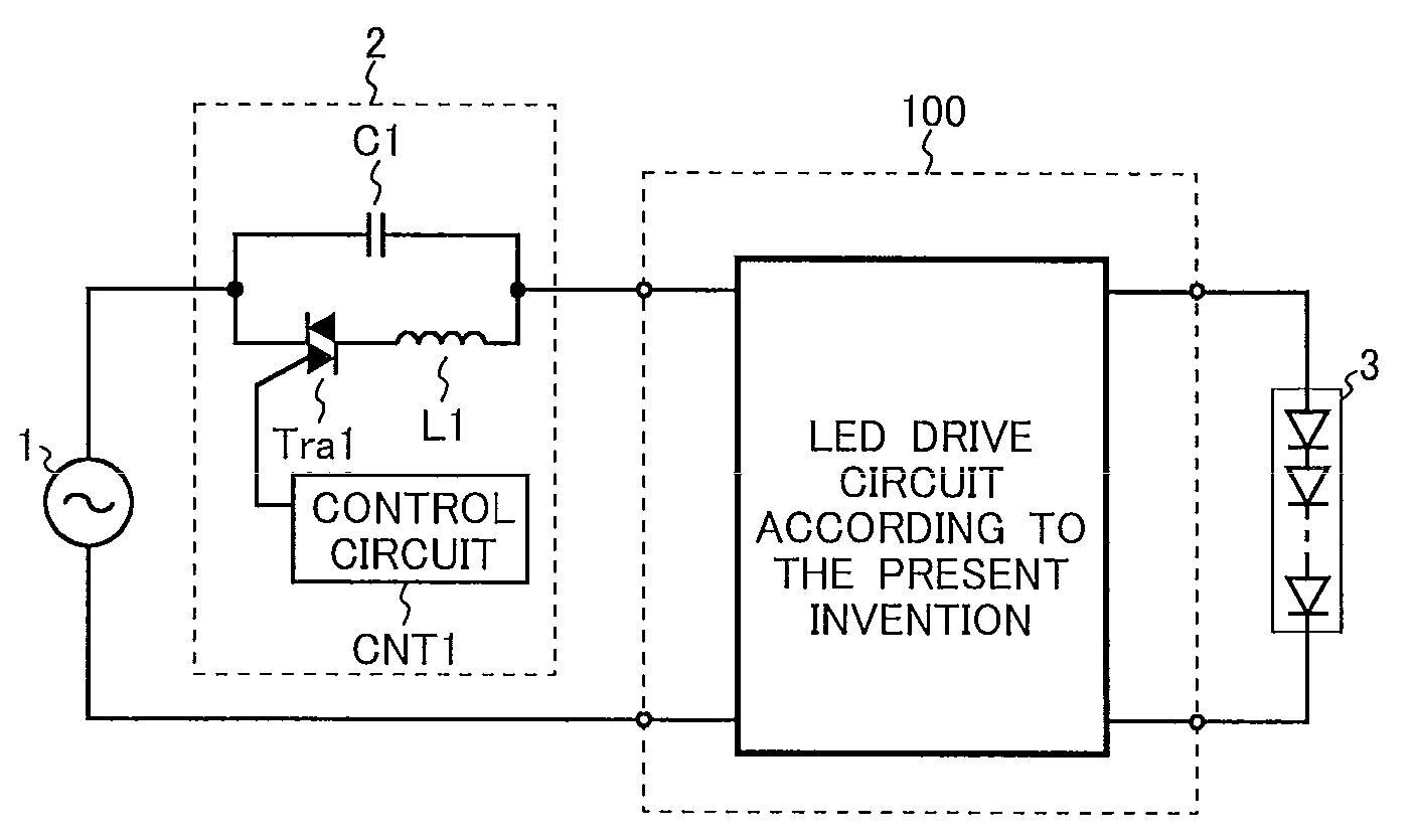
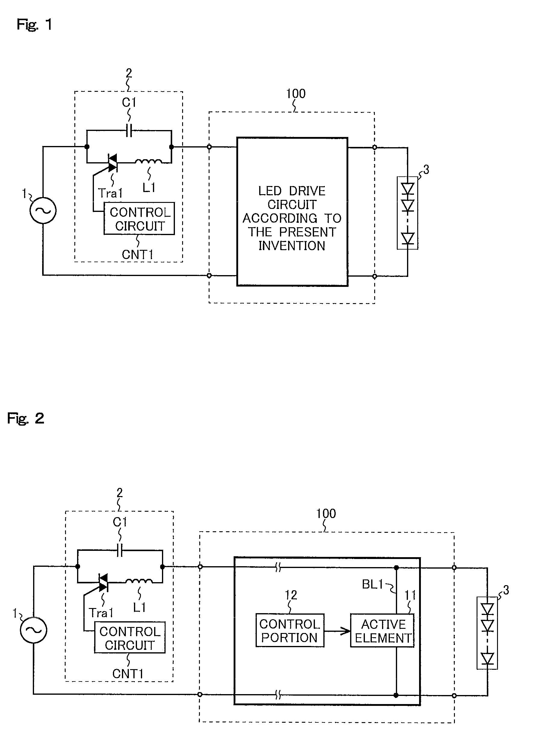
[0061]The embodiments of the present invention will be described below with reference to the drawings. A structural example of an LED illumination system according to the present invention is shown in FIG. 1. The LED illumination system according to the present invention shown in FIG. 1 includes: a phase-control light controller 2; an LED drive circuit 100 according to the present invention 100; and an LED module 3. In the LED illumination system according to the present invention shown in FIG. 1, an alternating-current power source 1, the phase-control light controller 2 and the LED drive circuit 100 according to the present invention are connected in series with each other. An anode and a cathode of the LED module 3 that includes one or more LEDs are connected to an output side of the LED drive circuit 100 according to the present invention.
[0062]Even if a TRIAC Tra1 is in an off state, a current that corresponds to a frequency (50 Hz or 60 Hz) of the alternating-current power sou...
PUM
 Abstract
Description
Claims
Application Information