Motor magnetic pole position detecting device

a technology of position sensor and detection device, which is applied in the direction of motor/generator/converter stopper, electronic commutator, dynamo-electric converter control, etc., can solve the problems of increasing production cost, increasing the wiring connection between the position sensor and the control device, and reducing reliability

Active Publication Date: 2010-04-15
KK TOSHIBA
View PDF9 Cites 16 Cited by
  • Summary
  • Abstract
  • Description
  • Claims
  • Application Information

AI Technical Summary

Benefits of technology

[0009]Therefore, an object of the present invention is to provide a motor magnetic pole position detecting device which can perform the positional detection successfully even when the motor has a small salience ratio or magnetic saturation occurs in the motor.
[0012]According to each above-described arrangement, when the detection AC current or voltage command is generated, a temporal change in the inductance obtained by the inductance calculation unit has a frequency component of a difference between a rotational frequency of the motor and any rotational frequency determining a phase angle supplied to the coordinate conversion unit. Furthermore, since the inductance of the motor having the magnetic saliency contains information about a motor magnetic pole position, the magnetic pole position detection section carries out an operation to obtain a frequency and phase of the inductance, so that the magnetic pole position of the motor can be obtained. Accordingly, the magnetic pole position can reliably be detected even when the motor has a relatively smaller salience ratio or the motor is in a magnetically saturated state.

Problems solved by technology

However, addition of a position sensor results in a problem of increasing production costs, a problem that an arrangement space needs to be ensured for the position sensor, and a problem of increase in the wiring for connecting between the position sensor and a control device.
Furthermore, there arises a problem of reduction in the reliability due to possible occurrence of breaking or disconnection or a problem of maintenance.
However, there is a problem that the position detection cannot be executed in a stopped state where no induced voltage is generated or in a very low speed range in which voltage amplitude is too small.
Accordingly, a clear distribution is obtained from a motor having a larger salience ratio (Lq / Ld) but in the motor having a smaller salience ratio, an inductance distribution is buried in an electrical or mechanical error of the motor or calculating error in a calculating unit, whereupon there is a problem that the position detection becomes difficult.
As a result, too, the position detection becomes difficult.

Method used


Image

  • Motor magnetic pole position detecting device
  • Motor magnetic pole position detecting device
  • Motor magnetic pole position detecting device

Examples


first embodiment

[0028]the present invention will be described with reference to FIGS. 1 to 13. Referring first to FIG. 12, an embedded permanent magnet motor (interior permanent magnet (IPM) motor) is shown. The permanent magnet motor comprises a stator 1 and a rotor 10. The stator 1 includes a stator core 3 having a number of radially arranged teeth 2, resin 4 that is molded so as to cover the stator core 3, and a stator winding 5 wound on the teeth 2. The stator core 3 is formed by stacking a plurality of steel sheets. The stator 1 is provided with a mounting portion 6 which is to be mounted on a predetermined portion of a washing machine.

[0029]The stator 1 includes a generally vessel-shaped frame 11 made of a magnetic material, an annular rotor core 12 disposed on an inner circumference of an annular wall 11a formed at the open side of the frame 11, a number of field system permanent magnets 14 (neodymium magnets, for example), and a molding resin 15 molded so that the rotor core 12, permanent m...

second embodiment

[0079] the motor control device 63 can further be arranged more easily since the first current control section 46 is de-necessitated.

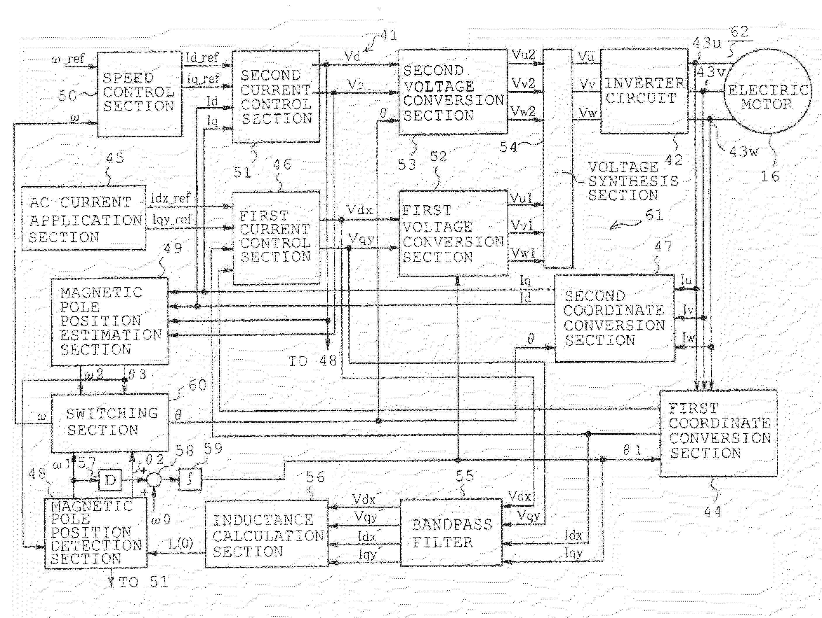
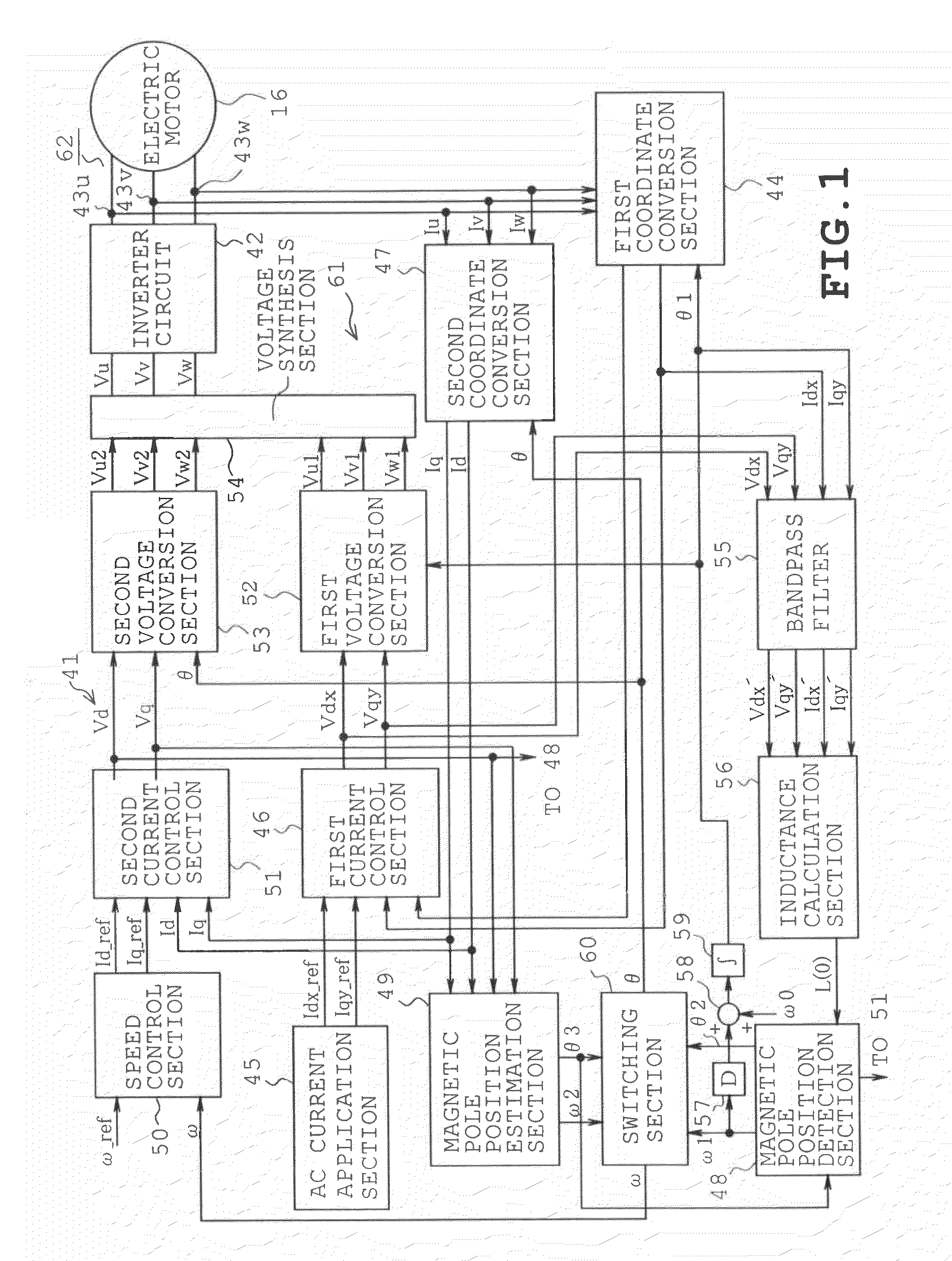
[0080]The foregoing embodiments are not restrictive but and may be modified or expanded as follows. All three-phase currents need not be detected. Only two-phase currents may be detected and the other phase current may be obtained by calculation, instead.

[0081]The phase angle θ1 supplied to the first coordinate conversion section 44 may not be set based on the motor frequency col. The phase angle may be based on a frequency differing from a rotational frequency of the motor 16. Furthermore, when the motor 16 is being rotated, the rotation of observation coordinate system may be stopped without supply of the phase angle θ1.

[0082]The arrangement only estimating the magnetic pole position of the motor de-necessitates the second coordinate conversion section 47, magnetic pole position estimation section 49, speed control section 50, second current control ...


PUM


Abstract

A motor magnetic pole position detecting device includes a detection current command generation unit generating a detection AC current command, a current detection section detecting a current flowing into the motor, a coordinate conversion unit vector-converting the current detected by the current detection section into an excitation component and a torque component both represented by a d-q orthogonal coordinate system based on a phase angle obtained at any rotational frequency, a current control unit delivering a voltage command to current-control the motor based on the detection current command and the current converted by the coordinate conversion unit, an inductance calculation unit calculating motor inductance based on the voltage command and the current converted by the coordinate conversion unit, and a magnetic pole position detection section calculating a frequency and phase of the inductance calculated by the inductance calculation unit, converting the inductance phase into a motor magnetic pole position.

Description

CROSS-REFERENCE TO RELATED APPLICATIONS[0001]This application is based on and claims the benefit of priority from the prior Japanese Patent Application No. 2008-262793, filed on Oct. 9, 2008, the entire contents of which are incorporated herein by reference.BACKGROUND[0002]1. Field[0003]The present invention relates to a device which detects a magnetic pole position of a permanent magnet motor having a magnetic saliency.[0004]2. Related Art[0005]Recent washing machines and the like have employed an arrangement of vector control for a permanent magnet motor for the purpose of improving a precision in rotational control or washing performance. As a result, power consumption and an amount of vibration produced during the operation have been reduced in the washing machines and the like. Electrical current is controlled according to a position of magnetic pole of a permanent magnet motor when the vector control is applied to the motor for control in high precision and high rotational spe...

Claims


Application Information

Patent Timeline
Patent Type & Authority Applications(United States)
IPC IPC(8): H02P6/18H02P6/06H02P6/08H02P6/17H02P6/182H02P6/185H02P6/28
CPCH02P6/18
Inventor MAEKAWA, SARI
Owner KK TOSHIBA
Why Eureka
Try Eureka