
Hybrid-type polarizer, method of manufacturing the same and display device having the same

a technology of hybrid polarizers and display devices, applied in the direction of polarising elements, instruments, optical elements, etc., can solve the problems of reducing the luminance of the lcd device, and more of the generated light is lost. , to achieve the effect of improving the image display quality of the display device and reducing the manufacturing cost of the display devi

Inactive Publication Date: 2010-04-15
KIM WOO JUN +2
View PDF8 Cites 21 Cited by
  • Summary
  • Abstract
  • Description
  • Claims
  • Application Information

AI Technical Summary

Benefits of technology

[0009]The present invention provides a hybrid-type polarizer having a reflective-type polarizing filter and a color filter capable of improving polarizing characteristics such as a polarization extinction ratio and a reflective ratio.
[0018]According to the present invention, the hybrid-type polarizer has a mono-layered structure that functions as a reflective-type polarizing filter and a color filter to improve the image display quality of a display device. The hybrid-type polarizer may have the metal grating having a micro-structure. Using the hybrid-type polarizer decreases the manufacturing cost of the display device.

Problems solved by technology

Although energy is consumed to generate the blocked portion of the light, the blocked portion does not contribute to the image that is displayed and therefore represents a “waste.” More of the generated light is lost when it passes through the polarizer but is blocked by red, green and blue sub-pixels that form a unit pixel.
However, the reflective-type polarizer, the reflective-type color filter and the polarizer having the cholesteric liquid crystal also transmit only a portion of the light having a predetermined wavelength range, and block the remaining portion of the light having different wavelengths.
Thus, even with these techniques, much of the light ends up not contributing to the luminance of the LCD device.

Method used


Image

  • Hybrid-type polarizer, method of manufacturing the same and display device having the same
  • Hybrid-type polarizer, method of manufacturing the same and display device having the same
  • Hybrid-type polarizer, method of manufacturing the same and display device having the same

Examples


Embodiment Construction

[0030]The invention is described more fully hereinafter with reference to the accompanying drawings, in which embodiments of the invention are shown. This invention may, however, be embodied in many different forms and should not be construed as limited to the embodiments set forth herein. Rather, these embodiments are provided so that this disclosure will be thorough and complete, and will fully convey the scope of the invention to those skilled in the art. In the drawings, the size and relative sizes of layers and regions may be exaggerated for clarity.

[0031]It will be understood that when an element or layer is referred to as being “on,”“attached to,”“connected to,” or “coupled to” another element or layer, it can be directly on, attached, connected or coupled to the other element or layer or intervening elements or layers may be present. Like numbers refer to like elements throughout. As used herein, the term “and / or” includes any and all combinations of one or more of the assoc...


PUM

PropertyMeasurementUnit
first order diffraction angleaaaaaaaaaa
refractive indexaaaaaaaaaa
light transmittanceaaaaaaaaaa

Abstract

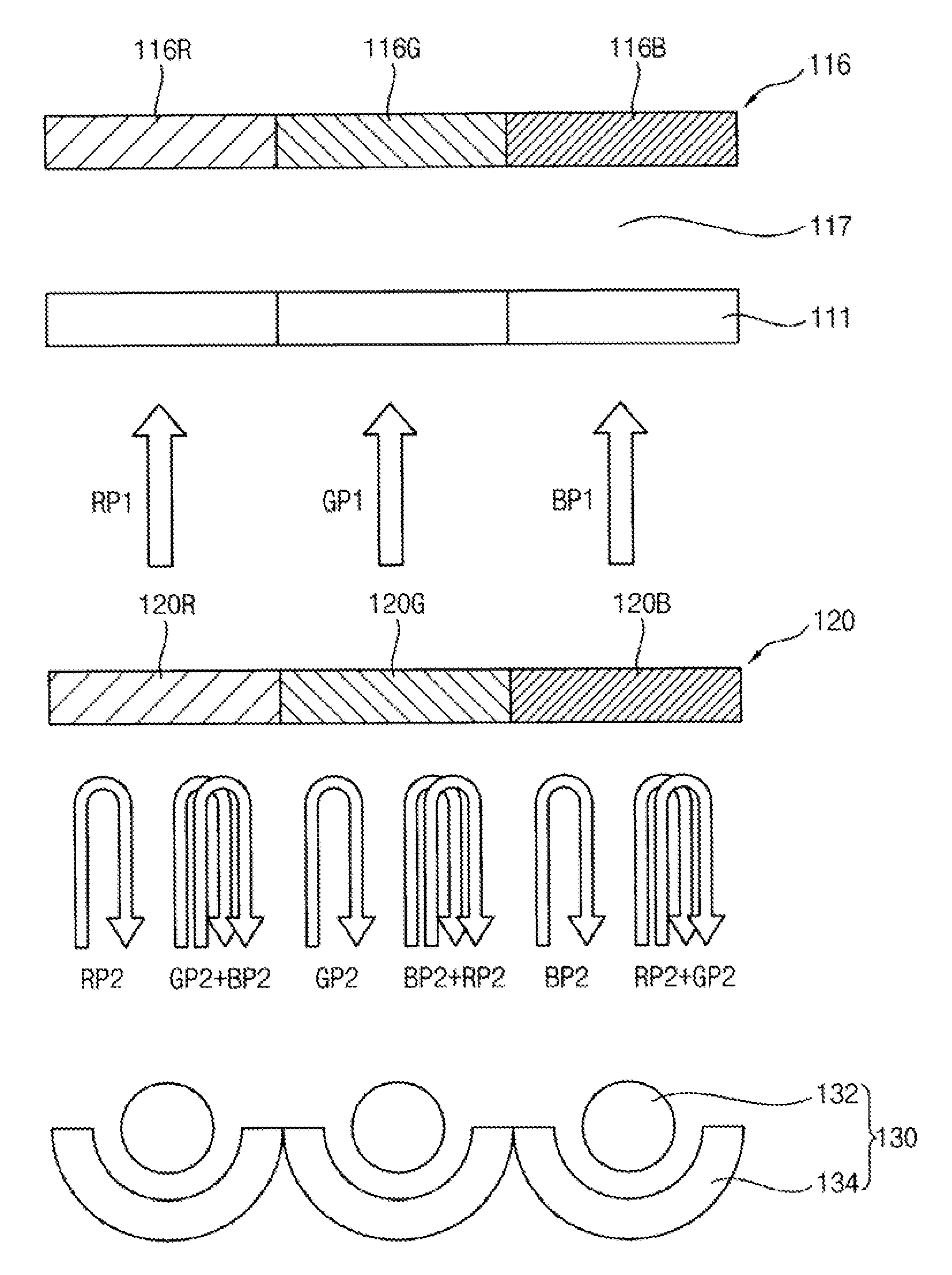
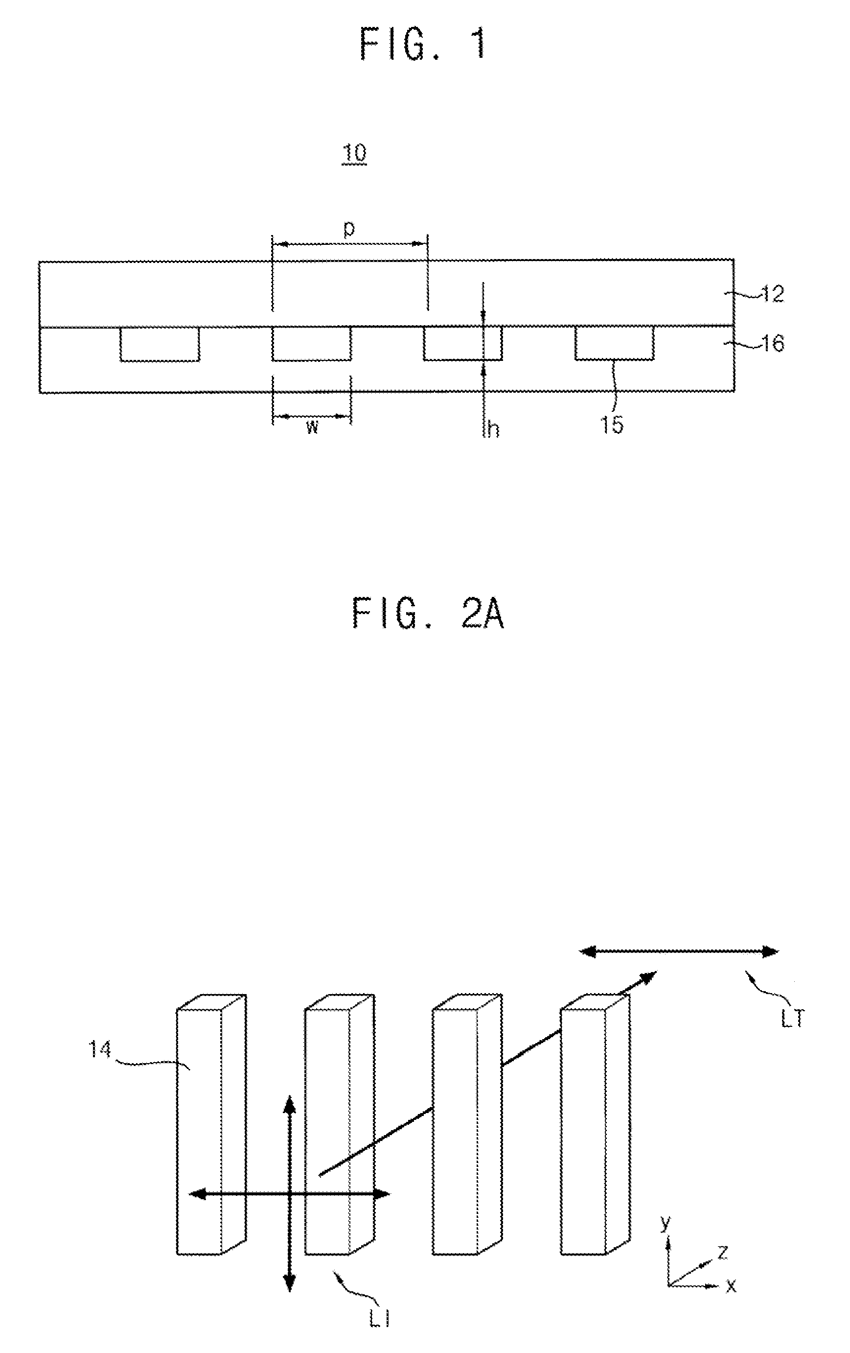
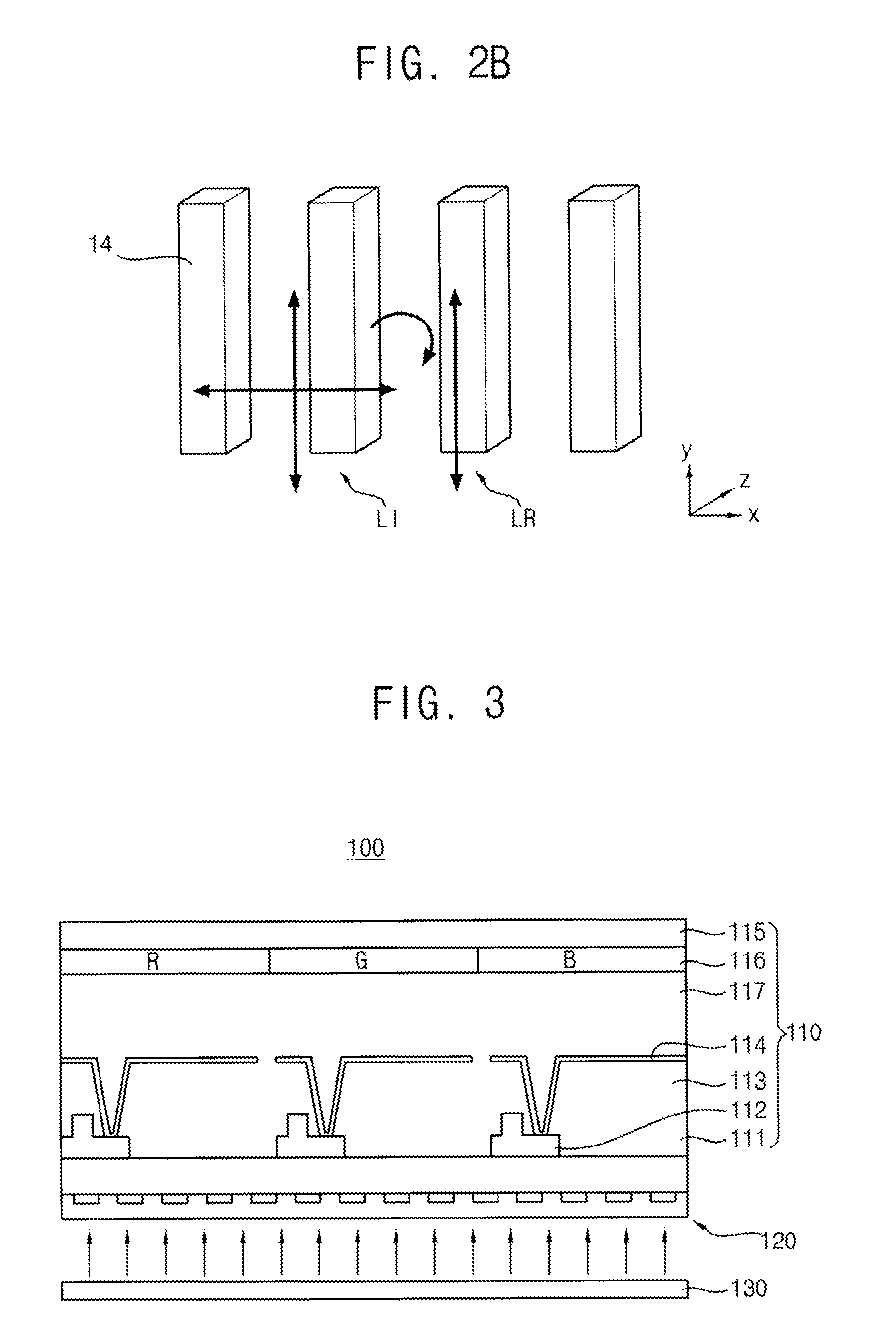
In a hybrid-type polarizer having a reflective-type polarizing filter and a color filter, a method of manufacturing the hybrid-type polarizer and a display device having the hybrid-type polarizer, the hybrid-type polarizer includes a base member and a polarizing color filter member. The polarizing color filter member includes a plurality of metal gratings in a plurality of regions of the base member. The metal gratings in the regions have different sizes from each other. Each of the metal gratings transmits a first portion of an incident light and reflects a second portion of the incident light. The invention improves image display quality and lowers the manufacturing cost.

Description

CROSS-REFERENCE TO RELATED APPLICATION[0001]The present application is a Divisional of U.S. patent application Ser. No. 11 / 490,222 filed on Jul. 19, 2006 which claims priority from Korean Patent Application No. 2005-65078, filed on Jul. 19, 2005, the disclosures of which are hereby incorporated herein by reference in its entirety.BACKGROUND OF THE INVENTION[0002]1. Field of the Invention[0003]The present invention relates generally to a hybrid-type polarizer and more particularly to a hybrid-type polarizer having a reflective-type polarizing filter and a color filter.[0004]2. Description of the Related Art[0005]While liquid crystal display (LCD) devices are popular flat panel displays with many advantages, there are aspects of these devices that could be improved. For example, the efficiency with which light is used for the display could be higher. An LCD device displays an image using the polarizing characteristics of liquid crystals, and often includes one or more polarizers to co...

Claims


Application Information

Patent Timeline
Patent Type & Authority Applications(United States)
IPC IPC(8): G02F1/1335G02B5/30B29D11/00
CPCG02B5/3058G02F1/133536G02F1/133533G02F1/133514G02F1/1335
Inventor KIM, WOO-JUNJANG, TAE-SEOKCHOI, JIN-SUNG
Owner KIM WOO JUN
Learn More