Base station apparatus and communication control method

a communication control and base station technology, applied in the field of mobile communication systems, can solve problems such as communication quality degradation, user equipment may not be able to correctly decode identification information, and communication using the shared channel may not be performed

Inactive Publication Date: 2010-04-15
NTT DOCOMO INC
View PDF4 Cites 98 Cited by
  • Summary
  • Abstract
  • Description
  • Claims
  • Application Information

AI Technical Summary

Benefits of technology

[0035]According to an embodiment of the present invention, there may be provided a base station apparatus and a communication control method capable of adequately performing the transmission power control of the identification information of the user equipment communicating using the sub-frame of the shared channel and the information indicating the transmission format of the shared channel.

Problems solved by technology

However, among the information items transmitted in the PDCCH, if the data of the Downlink Scheduling Information or the Uplink Scheduling Grant, namely, the information indicating the identification of the user equipment communicating using the shared channel in the sub-frame and the transmission format of the shared channel are wrongly transmitted, the shared channel may not be transmitted and as a result, the communications quality may be degraded.
For example, as a result of the transmission power control, when the transmission power allocated to the transmission of the identification information of the user equipment communicating using the shared channel in the sub-frame and the transmission of the information indicating the transmission format of the shared channel are less than necessary, the user equipment may not be able to correctly decode the identification information of the user equipment communicating using the shared channel in the sub-frame and the information indicating the transmission format of the shared channel, and as a result, the communications using the shared channel may not be performed.

Method used


Image

  • Base station apparatus and communication control method
  • Base station apparatus and communication control method
  • Base station apparatus and communication control method

Examples


Embodiment Construction

[0052]208: BASEBAND SIGNAL PROCESSING SECTION

[0053]210: CALL PROCESSING SECTION

[0054]212: CHANNEL INTERFACE

[0055]2081: LAYER 1 PROCESSING SECTION

[0056]2082: MAC PROCESSING SECTION

[0057]2083: RLC PROCESSING SECTION

[0058]2084: DL TRANSMISSION POWER DETERMINATION SECTION

[0059]300: ACCESS GATEWAY

[0060]400: CORE NETWORK

BEST MODE FOR CARRYING OUT THE INVENTION

[0061]Next, a best mode for carrying out the present invention is described based on the embodiments described below with reference to the accompanying drawings.

[0062]Throughout the figures for illustrating the embodiments of the present invention, the same reference numerals are used for the same or equivalent elements and the repeated descriptions thereof may be omitted.

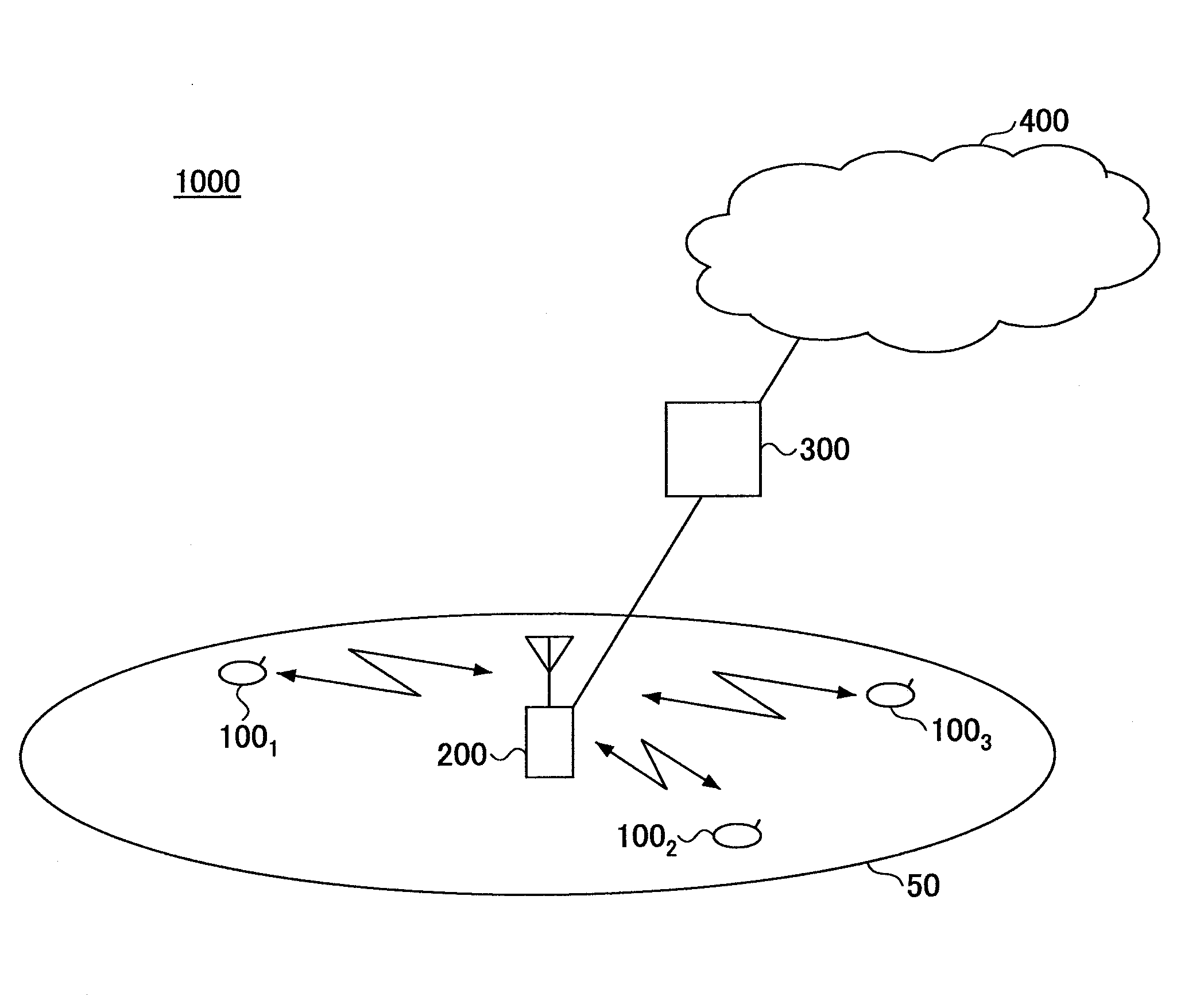
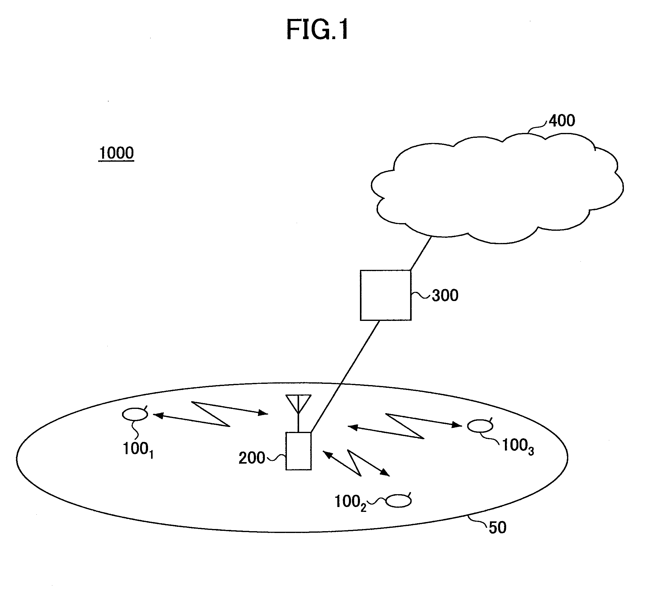
[0063]First, a radio communication system having a base station apparatus according to an embodiment of the present invention is described with reference to FIG. 1.

[0064]As shown in FIG. 1, the radio communication system 1000, which may be an Evolved UTRA (Universal...


PUM


Abstract

A base station apparatus is disclosed that includes a selection unit selecting user equipment terminals to which radio resources are allocated based on priority levels indicating a priority order of allocating the radio resources for a shared channel and a resource determination unit determining a transmission power level of a control channel and resources for the control channel, the control channel indicating communications of the shared channel to the selected user equipment terminals. In the base station apparatus, when the sum of the transmission power of the control channel related to the selected user equipment terminals exceeds a predetermined first threshold value or when a sum of control resources for the control channel related to the selected user equipment terminals exceeds a predetermined second threshold value, the resource determination unit transmits the control channel to some user equipment terminals among the selected user equipment terminals.

Description

TECHNICAL FIELD[0001]The present invention generally relates to a mobile communication system employing an Orthogonal Frequency Division Multiplexing (OFDM) scheme, and more particularly to a base station apparatus and a communication control method.BACKGROUND ART[0002]As a next-generation system of the W-CDMA[0003](Wideband Code Division Multiple Access) and the HSDPA (High Speed Downlink Packet Access), an LTE system has been studied by 3GPP (3rd Generation Partnership Project) which is a standards body of the W-CDMA. In the LTE system as a radio access system, an OFDM (Orthogonal Frequency Division Multiplexing) scheme and an SC-FDMA (Single-Carrier Frequency Division Multiple Access) scheme have been studied to be applied to the downlink communications system and the uplink communication system, respectively (see, for example, Non Patent[0004]Document 1).[0005]In the OFDM scheme, a frequency band is divided into plural sub-carriers having narrower frequency bands, and data are t...

Claims


Application Information

Patent Timeline
Patent Type & Authority Applications(United States)
IPC IPC(8): H04W72/04H04W36/00
CPCH04W52/32H04W52/34H04W72/1247H04L5/0037H04L5/0053H04L5/0007H04W72/566H04W88/08H04W72/56
Inventor ISHII, HIROYUKIHIGUCHI, KENICHI
Owner NTT DOCOMO INC
Why Eureka
Try Eureka