Coding rate conversion apparatus, coding rate conversion method, and integrated circuit

a coding rate and conversion method technology, applied in the field of converting a coding rate, can solve the problems of not being able to achieve not being able to achieve being unable to achieve the effect of reducing the quantization error of the output stream, suppressing image quality degradation, and reducing the quantization error of the quantization

Inactive Publication Date: 2010-04-15
PANASONIC CORP
View PDF6 Cites 60 Cited by
  • Summary
  • Abstract
  • Description
  • Claims
  • Application Information

AI Technical Summary

Benefits of technology

[0111]Suppose the converted scale used for the quantization is a value obtained by multiplying the quantization scale corresponding to at least one macroblock by 1. In such a case, all coefficients (coefficients of low frequency components and high frequency components) in the second quantization matrix used for the quantization are unchanged.
[0112]Accordingly, by performing the quantization using the second quantization matrix in which the low frequency coefficient is smaller than the high frequency coefficient, the occurrence of quantization errors in low frequency components can be suppressed, and also the occurrence of quantization errors in high frequency components in at least one macroblock can be suppressed. This makes it possible to suppress image quality degradation caused by quantization errors in low frequency components, and further suppress image quality degradation caused by quantization errors in high frequency components in a specific macroblock.
[0114]According to the present invention, a plurality of macroblocks constituting coded data are inverse quantized using a first quantization matrix that is used when coding a picture, to obtain a plurality of sets of coefficient data. The first quantization matrix is converted to a second quantization matrix so that, among a plurality of coefficients shown by the first quantization matrix, a low frequency coefficient corresponding to a frequency lower than a predetermined frequency becomes smaller than a high frequency coefficient. When the second quantization matrix is a matrix for increasing a coding rate of the coded data, a converted scale is calculated by multiplying a quantization scale corresponding to at least one macroblock by −1 (≧1). At least one part of the plurality of sets of coefficient data is quantized using the second quantization matrix and a calculated converted scale that corresponds to a macroblock corresponding to the at least one part of the plurality of sets of coefficient data.
[0115]Which is to say, the second quantization matrix used for the quantization is a matrix in which the low frequency coefficient corresponding to the frequency lower than the predetermined frequency is smaller than the high frequency coefficient. When coefficients in the quantization matrix used for the quantization are smaller, quantization errors in the quantization are smaller.
[0116]Moreover, when the second quantization matrix is a matrix for increasing the coding rate of the coded data, the converted scale calculated by multiplying the quantization scale corresponding to at least one macroblock by β1 (≧1) is used for the quantization. Note that all coefficients of the quantization matrix are multiplied by the quantization scale. Therefore, when the quantization scale is smaller, quantization errors in the quantization are smaller.

Problems solved by technology

However, it is not necessarily desirable to use the quantization scale itself in coding rate conversion.
However, as long as converting the input stream and outputting the converted stream as the output stream, it is impossible that the output stream has smaller quantization errors than the input stream.
Therefore, this increase in bit amount is totally meaningless.
The conversion to the integers (dropping the fractional portions), however, causes errors (quantization errors).
This being so, there is a possibility that errors uniformly occur in all frequencies from low frequency components to high frequency components.
In particular, the human eye is extremely sensitive to errors in low frequency components, and these errors are observed as block noise.
This incurs a possibility that block noise due to the aforementioned errors in low frequency components occurs extensively.
On the other hand, though the quantization scale reconversion-type coding rate conversion apparatus 11000 uses Step 2 of TM5 for the control in units of macroblocks, this is a method for changing the quantization scale, and therefore cannot be applied to the quantization matrix reconversion-type coding rate conversion method.
In the coding rate conversion apparatus 12000, however, since the quantization matrix can be set only in units of pictures, the coding rate cannot be controlled finely, and in the worst case the coding rate can only be converged to the target rate after several tens of pictures.
However, the coding rate conversion apparatus 12000 cannot meet this requirement, and image distortion may be caused by distributing a stream that exceeds the network bandwidth over a predetermined time period.
The coding rate conversion apparatus 12000 has difficulty in realizing this control, and there is even a possibility that a stream violating the standard is outputted.

Method used


Image

  • Coding rate conversion apparatus, coding rate conversion method, and integrated circuit
  • Coding rate conversion apparatus, coding rate conversion method, and integrated circuit
  • Coding rate conversion apparatus, coding rate conversion method, and integrated circuit

Examples


first embodiment

[0181]The following describes an embodiment of the present invention, with reference to drawings.

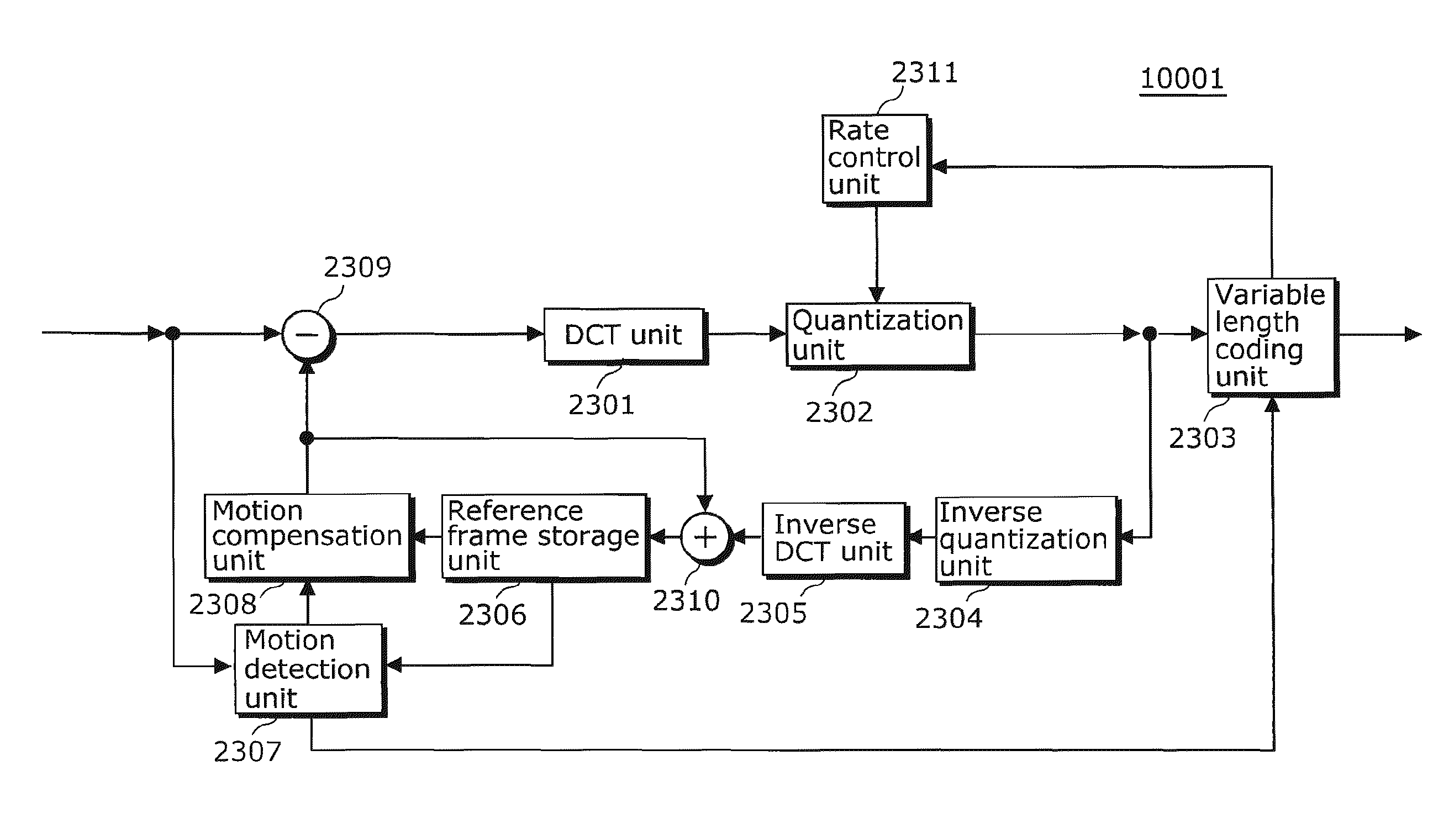
[0182]FIG. 11 is a block diagram showing a structure of a coding rate conversion apparatus 1000 in a first embodiment of the present invention.

[0183]The coding rate conversion apparatus 1000 includes a variable length decoding unit 101, a variable length coding unit 102, a rate control unit 103, a quantization scale increase conversion unit 104, an MB header storage unit 105, a quantization matrix low-range decrease conversion unit 108, a picture header storage unit 109, and a quantization matrix conversion control unit 110.

[0184]The variable length decoding unit 101 receives an input of a stream for restoring a plurality of pictures. Hereafter, the stream inputted in the variable length decoding unit 101 is referred to as an input stream. The input stream is coded data obtained by coding the pictures. The variable length decoding unit 101 decodes an MPEG2 stream as the input stream, and...

second embodiment

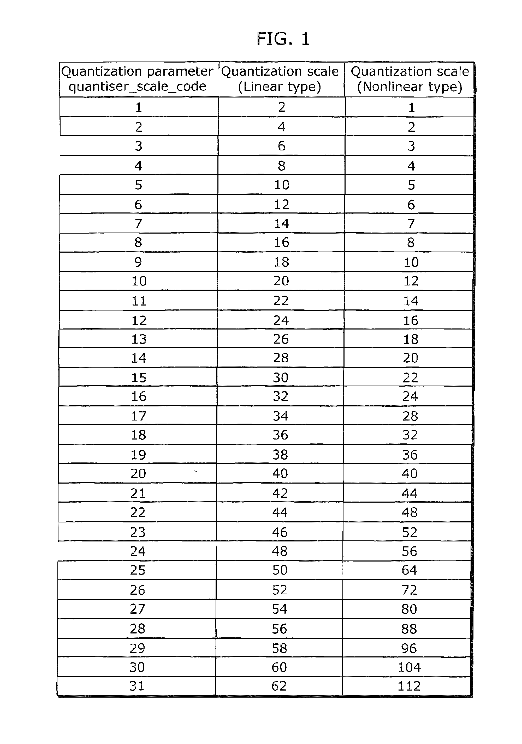
[0315]In the coding rate conversion apparatus 1000 of the first embodiment, the quantization scale can take the value only in the range of 1 to 112 in, for example, MPEG2. Accordingly, when the quantization scale of the input stream is close to 112, quantization scale conversion factor β cannot be made larger. This makes it impossible to compensate for the code amount increase in low frequency components by the quantization matrix, as a result of which the coding rate cannot be reduced sufficiently.

[0316]In addition, in the coding rate conversion apparatus 1000 of the first embodiment, each coefficient of the quantization matrix can take the value only in the range of 1 to 255 in MPEG2. Accordingly, when coefficients of low frequency components in the quantization matrix of the input stream are already close to 1 to some extent, quantization matrix conversion factor α of low frequency components cannot be made larger. In such a case, image quality degradation cannot be reduced suffi...

third embodiment

[0396]In the coding rate conversion apparatus 1000A of the second embodiment, the quantization matrix can take the value only in the range of 1 to 255 in MPEG2. Accordingly, when coefficients of the high range (high frequency components) in the quantization matrix of the input stream are already close to 255, quantization matrix conversion factor α of high frequency components cannot be made larger. This makes it impossible to sufficiently reduce the code amount of high frequency components, as a result of which the coding rate cannot be reduced sufficiently.

[0397]In addition, in the coding rate conversion apparatus 1000A of the second embodiment, the quantization scale can take the value only in the range of 1 to 112 in MPEG2. Accordingly, when the quantization scale of the input stream is already close to 1, quantization scale conversion factor β in the significant MB cannot be made sufficiently small. This incurs a failure to suppress quantization errors caused by the high-range ...


PUM


Abstract

A plurality of macroblocks constituting coded data are inverse quantized using a first quantization matrix that is used when coding a picture, to obtain a plurality of sets of coefficient data. The first quantization matrix is converted to a second quantization matrix using a first conversion value and a second conversion value, where the first conversion value is for converting a low frequency coefficient corresponding to a frequency lower than a predetermined frequency among a plurality of coefficients shown by the first quantization matrix, and the second conversion value is for converting a high frequency coefficient among the plurality of coefficients and is larger than the first conversion value (Step S408). When the second quantization matrix is a matrix for increasing a coding rate of the coded data, a converted scale is calculated by multiplying a quantization scale corresponding to at least one macroblock by β1 (≧1). At least one part of the plurality of sets of coefficient data is quantized using the second quantization matrix and a calculated converted scale that corresponds to a macroblock corresponding to the at least one part of the plurality of sets of coefficient data.

Description

TECHNICAL FIELD[0001]The present invention relates to a technique of converting a coding rate for a further reduction in information amount of coded data, and more specifically relates to a coding rate conversion apparatus and the like that suppress image quality degradation accompanying coding rate conversion.BACKGROUND ART[0002]In recent years, Moving Picture Experts Group 2 (MPEG2) that achieves high compression is adopted as an image coding is technique. This technique is applied to digital broadcasting, DVDs, networks, and other recording media, and bitrates can be selected within a predetermined range according to applications.[0003]For example, when selecting a bitrate for recording a digital broadcast of high image quality on a recording medium, more data can be recorded on the recording medium by converting a coding rate for a lower bitrate in order to reduce the information amount, instead of recording the data of high image quality directly on the recording medium. There ...

Claims


Application Information

Patent Timeline
Patent Type & Authority Applications(United States)
IPC IPC(8): H04N7/26
CPCH04N19/176H04N19/15H04N19/129H04N19/93H04N19/124H04N19/184H04N19/61
Inventor IKEDA, HIROSHIWADA, YOSHIYUKI
Owner PANASONIC CORP
Why Eureka
Try Eureka