Artificial joint replacement assisting device, artificial joint replacement assisting method using same, and assisting system

a technology of artificial joint replacement and assisting device, which is applied in the direction of osteosynthesis device, prosthesis, instruments, etc., can solve the problems of inability to correct magnification ratio or reduction ratio, inability to take radiographs, inaccurate position of bone resection plane determined by conventional templating, etc., and achieve accurate determination and adequate implant position. , the effect of accurate determination

Inactive Publication Date: 2010-04-15
TATSUMI ICHIRO +1
View PDF5 Cites 5 Cited by
  • Summary
  • Abstract
  • Description
  • Claims
  • Application Information

AI Technical Summary

Benefits of technology

[0068]According to the assisting method for artificial joint replacement and assisting system for artificial joint replacement or computer program according to the present invention as designed as mentioned above, after a relative three-dimensional position relation among an The source of X-ray, three-dimensional CAD data (10D) of the assisting device for artificial joint replacement (10) and a frontal radiograph (relation among frontal three elements) and a relative three-dimensional position relation among an The source of X-ray, three-dimensional CAD data (10D) of the assisting device for artificial joint replacement (10) and a lateral radiograph (relation among lateral three elements) are determined, a three-dimensional relative position relation among five elements, i.e., the frontal The source of X-ray (FS), plane (PS) belonging to the frontal radiograph, lateral The source of X-ray (FL), plane (PL) belonging to the lateral radiograph, and three-dimensional CAD data (10D) (three-dimensional position relation between the frontal three-element relation and the lateral three-element relation) is determined.
[0069]Therefore, according to the present invention, the three-dimensional position relation can be determined accurately even if the frontal radiograph is not exactly perpendicular to the lateral radiograph. Specifically, unlike the conventional case that a two-dimensional template is used, the three-dimensional position relation can be determined accurately even if the angle between the frontal radiograph and the lateral radiograph is not exactly 90 degrees (not perpendicular).
[0070]Furthermore, according to the present invention, when the three-dimensional position relations for the frontal radiograph and lateral radiograph have been determined, the adequate implant position can be determined. Specifically, if the implant images (IU, IL) as three-dimensional CAD data in one radiograph (for example, frontal radiograph) are moved, the implant images as three-dimensional CAD data in the other (for example, lateral radiograph) are also moved in conjunction therewith.
[0071]Besides, if a different size implant image (IU) as three-dimensional CAD data is projected in one radiograph (for example, frontal radiograph), an implant image of the different size as three-dimensional CAD data is also projected in the other radiograph (for example, lateral radiograph).
[0072]In the related art in which only two-dimensional templating can be performed, templating for the frontal radiograph and templating for the lateral radiograph must be performed separately in order to determine the adequate implant position and there are cases that the implant position in the frontal radiograph does not match that in the lateral radiograph three-dimensionally.
[0073]On the other hand, according to the present invention, when a three-dimensional relative position relation among five elements, i.e., the frontal The source of X-ray (FS), plane (PS) belonging to the frontal radiograph, lateral The source of X-ray (FL), plane (PL) belonging to the lateral radiograph, and three-dimensional CAD data (10D), (three-dimensional position relation between the frontal three-element relation and the lateral three-element relation) has been determined, the implant size and position with respect to the joint in the radiograph can be adjusted, namely three-dimensional templating can be performed.

Problems solved by technology

However, it is difficult to take radiographs so that the plane of a frontal radiograph and the plane of a lateral radiograph are in a relative position relation so as to be perpendicular to each other.
For this reason, there exists a problem that the position, etc. of the bone resection plane determined by conventional templating is inaccurate.
Besides, in conventional templating which uses a two-dimensional template, the magnification ratio or reduction ratio cannot be corrected.
In other words, there is a problem that conventional templating which uses a two-dimensional template is often not practically useful.
However, taking radiographs repeatedly involves the problem of radiation exposure of patients.
In addition, in case of a knee joint, if the patient has a flexion contracture in the knee, it is difficult even to take radiographs for conventional templating which uses a two-dimensional template.
For a joint with a flexion contracture, the magnification ratio must be varied with regions of the joint, making it difficult to adjust the conventional two-dimensional template to the joint shown in the radiograph.
Although this conventional technique is useful, it cannot be said to be satisfactory to assist in artificial joint replacement.
Although this technique is also useful, it does not solve the above problem.

Method used


Image

  • Artificial joint replacement assisting device, artificial joint replacement assisting method using same, and assisting system
  • Artificial joint replacement assisting device, artificial joint replacement assisting method using same, and assisting system
  • Artificial joint replacement assisting device, artificial joint replacement assisting method using same, and assisting system

Examples


first embodiment

[0102]First, referring to FIGS. 3 to 13, the assisting method for artificial joint replacement and assisting system for artificial joint replacement are described below.

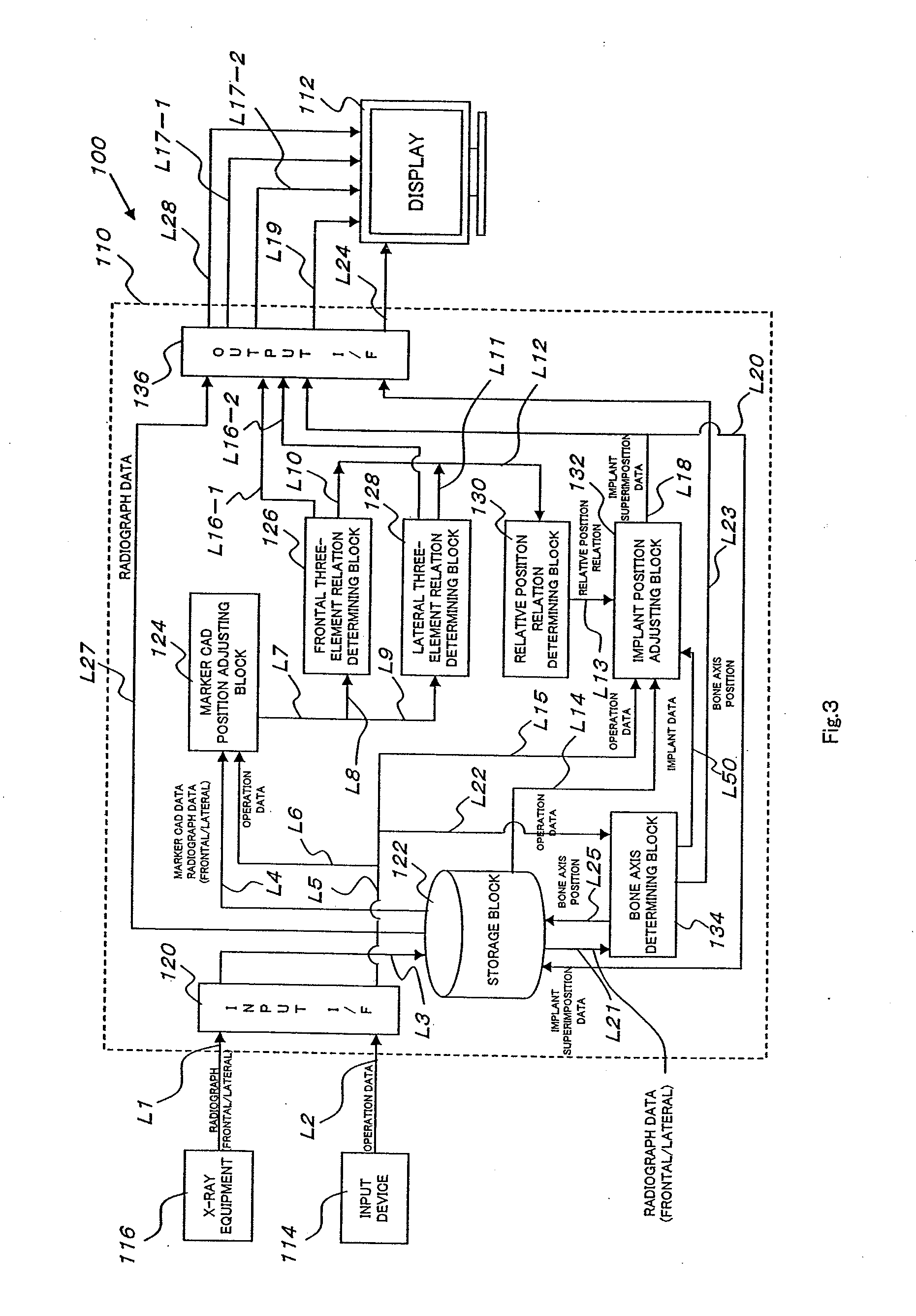
[0103]FIG. 3 is a bloc diagram of the assisting system for artificial joint replacement.

[0104]In FIG. 3, the assisting system for artificial joint replacement, the whole of which is designated by reference numeral 100, is mainly comprised of: a system main unit 110 composed of a computer; a display 112 as a display unit; input means 114 composed of a keyboard and a mouse or the like; and X-ray equipment 116 as a system for taking radiographs.

[0105]The system main unit 110 includes an input interface 120, a storage block 122 as a database, a marker CAD position adjusting block 124, a frontal three-element relation determining block 126 and a lateral three-element relation determining block 128, a relative position relation determining block 130, an implant position adjusting block 132, a bone axis determining block 1...

second embodiment

[0196]Next, referring to FIGS. 14 to 19, the assisting method for artificial joint replacement and assisting system for artificial joint replacement will be described.

[0197]In the first embodiment shown in FIGS. 3 to 13, it is difficult to accurately adjust the position of the implant around the bone axis (position in the direction indicated by arrow R in FIG. 19 (c)), the position of so-called the rotation of the implant.

[0198]The second embodiment shown in FIGS. 14 to 19 is designed so that the implant position relating to such “rotation” can be adjusted adequately.

[0199]FIG. 14 shows the system configuration according to the second embodiment.

[0200]Referring to FIG. 14, points which are different from the first embodiment shown in FIG. 3 are explained below.

[0201]In FIG. 14, the system according to the second embodiment, the whole of which is designated by reference numeral 200, includes a system main unit 210 composed of a computer, a display 112, an input device 114, and X-ray ...


PUM


Abstract

A technique of adequately determining the position of the bone resection plane of artificial joint replacement and the size of the implant. The three-dimensional relative position relation (the three-dimensional position relation between the relation among frontal three elements and the relation among lateral three elements) among the five elements, i.e., a frontal The source of X-ray (FS), the plane (PS) to which the frontal radiograph belongs, a lateral The source of X-ray (FL), the plane (PL) to which the lateral radiograph belongs, a lateral The source of X-ray (FL), the plane (PL) to which the lateral radiograph belongs, and three-dimensional CAD data is determined (S7), shade images (IU, IL) of three dimensional CAD data on the implant are superimposed in an adequate position shown in the radiograph, and the images are displayed on a display (112) (S9, S10).

Description

TECHNICAL FIELD[0001]The present invention relates to a surgical operation in which a joint of a patient with osteoarthritis or the like is replaced with an artificial joint, or artificial joint replacement. More particularly, the present invention relates to an assisting device for artificial joint replacement which is used to assist in such artificial joint replacement, and an assisting method for artificial joint replacement and an assisting system for artificial joint replacement which use the assisting device.BACKGROUND ART[0002]Osteoarthritis is a disease which progresses with aging and in our country in which aging society is expected, an increase in the number of patients with osteoarthritis is presumed.[0003]Artificial joint replacement is a surgical operation in which a joint of a patient with osteoarthritis or the like is bone resectiond, a bone surrounding the joint is resected and an implant is attached to the bone resection plane. It is often used particularly for aged...

Claims


Application Information

Patent Timeline
Patent Type & Authority Applications(United States)
IPC IPC(8): A61B17/58G06K9/00
CPCA61B17/155A61F2002/4633A61B19/54A61B2017/565A61B2019/501A61B2019/508A61B2019/5238A61B2019/524A61B2019/5255A61B2019/5265A61B2019/5289A61B2019/5291A61B2019/5466A61B2019/5483A61B2019/566A61F2/38A61F2/461A61B17/157A61B2090/3983A61B2034/101A61B2034/2055A61B2034/256A61B2090/364A61B2090/376A61B2034/108A61B2090/3762A61B2034/2065A61B2090/365A61B90/39A61B2090/3966
Inventor TATSUMI, ICHIROHIRAKAWA, KAZUOKITAMURA, YUGONAKAJIMA, SHINICHIMURAKAMI, AKIRA
Owner TATSUMI ICHIRO
Why Eureka
Try Eureka