
Steaming system

a steam vent and steaming technology, applied in the field of steaming systems, can solve the problems of clogging of steam vents, staining users' articles, complex mechanical dosing devices, etc., and achieve the effect of avoiding clogging of steam outlet openings

Inactive Publication Date: 2010-04-22
KONINKLIJKE PHILIPS ELECTRONICS NV
View PDF9 Cites 0 Cited by
  • Summary
  • Abstract
  • Description
  • Claims
  • Application Information

AI Technical Summary

Benefits of technology

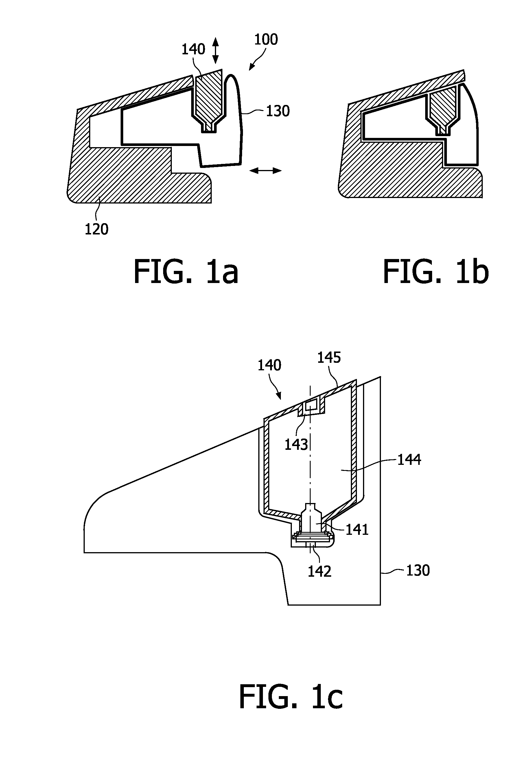
[0007]According to the invention, a steaming system comprises a steam generator, a removable water tank for holding and supplying water to the steam generator and a dosing device for supplying an amount of a water treatment agent to the water tank. The dosing device is configured to be triggered by a movement of the water tank relative to the steam generator. Each time the removable water tank is disengaged from or engaged to the steam generator, the dosing device is triggered and an amount of the water treatment agent is dosed into water tank. Disengaging the water tank usually means that a user wants to (completely) refill the (empty) water tank. Thus dosing of a predetermined amount of the water treatment agent is correlated to the re-filling of the water tank. This means that the concentration of the water treatment agent in the water tank remains constant. Such an automatic dosing ensures that the water is subjected at all times to an effective treatment without involving any additional action from the user. The water treatment agent provided in the dosing device minimizes the scale formation thereby improving the efficiency of the steam generator. It greatly reduces the frequency of rinsing of the steam generator, thus making the steaming system user-friendly.
[0008]According to an embodiment of the invention, the dosing device comprises a cartridge for holding the water treatment agent; a pump for pumping the water treatment agent from the cartridge to the water tank and a valve for balancing air pressure inside the cartridge while the water treatment agent is being pumped. The cartridge contains the water treatment agent intended to reduce the scale formation. The pump delivers the water treatment agent into the removable water tank upon being triggered by the movement of the water tank relative to the steam generator. This operation no longer requires any attention or special handling by a user to add the water treatment agent to the water. The valve provided in the dosing device balances the air pressure inside and outside the cartridge to ensure smooth functioning of the pump.
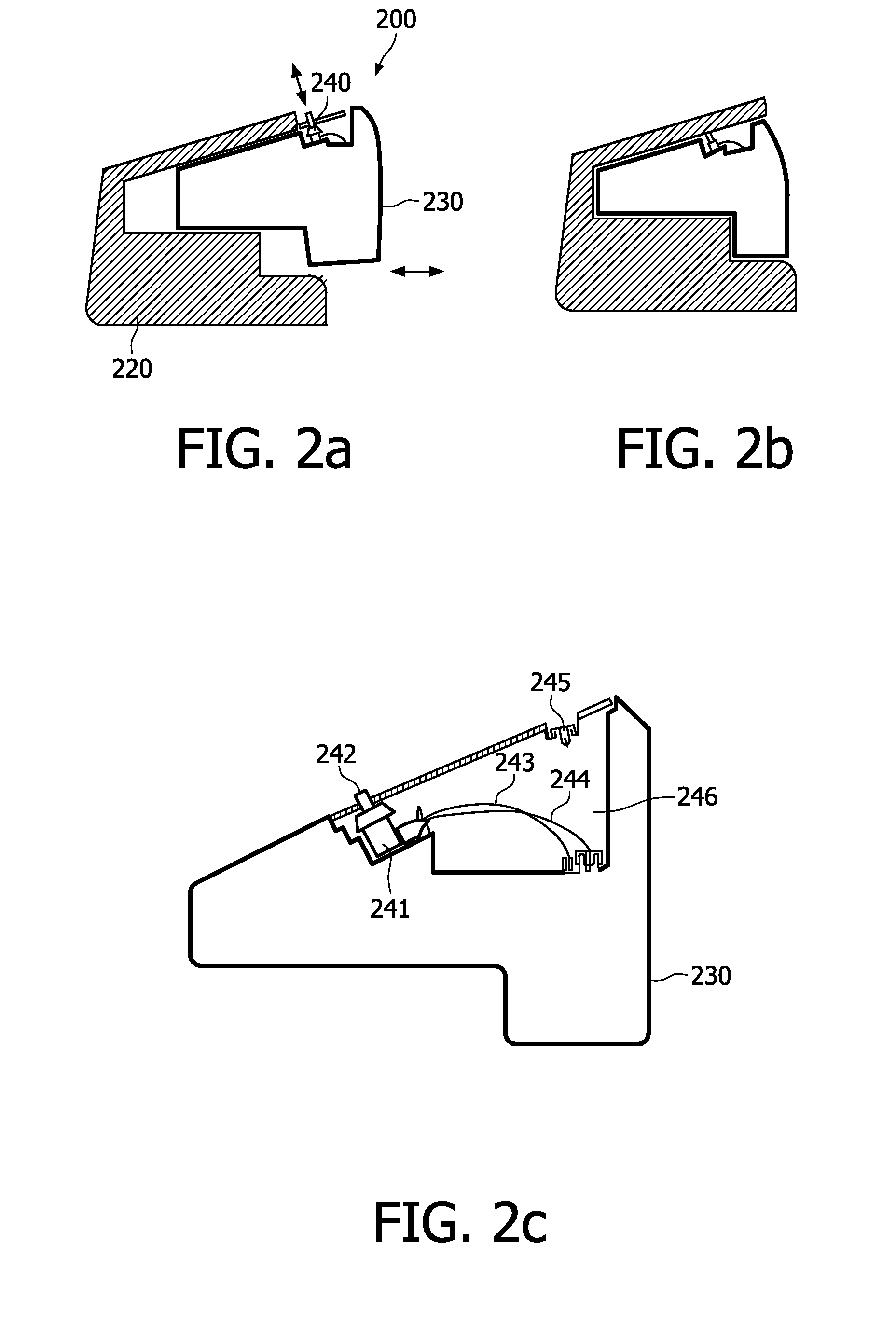
[0011]According to a further embodiment, the dosing device further comprises a sensor for sensing the movement of the water tank and for generating a signal. The dosing device also includes a control member for activating the pump based on the generated signal. These embodiments automate the process of adding a water treatment agent to the water used for steam generation.
[0013]According to yet another embodiment, an iron device comprises the steaming system as describe above. The steaming system ensures that there are no scale particles present in the steam generated and thus avoids the clogging of steam outlet openings made in the soleplate of the iron. The configuration of the steaming system described above also prevents the tanning of a garment to be ironed.

Problems solved by technology

The scale can be carried over with the steam to the outlet of the steam generator, causing the clogging of steam vents and staining users' articles.
In addition, the mechanical dosing device is complex and thus costly.

Method used


Image

  • Steaming system
  • Steaming system
  • Steaming system

Examples


first embodiment

[0029]According to the invention as shown in FIG. 1a to 1c, the water tank 130 is filled with water and is engaged to the steam generator 120. The housing 145 is pushed down when the water tank 130 is engaged to the steam generator 120. As a result the pump 141 gets activated to dose an amount of the water treatment agent into the water tank 130. The amount of water treatment agent needed is in the range of 1 to 500 ppm. Therefore, the amount of water treatment agent, sufficient for lifetime use of steaming system can be housed in the cartridge 144. The water treatment agent is preferably in the form of a solution containing a solute and water. The water treatment agent drips or flows into the water tank 130 through the outlet 142 and mixes with water therein. The one way valve 143 acts as a means to de-air in order to balance the air pressure inside and outside the dosing device 140 to ensure smooth functioning of the pump 141. The one way valve 143 lets the air into dosing device ...

second embodiment

[0031]According to the invention as shown in FIG. 2, the pump 241 is activated as the switch 242 gets pushed when the water tank 230 gets engaged to the steam generator 220. The one way valve 245 is provided to balance the air pressure inside and outside the dosing device 240 to ensure smooth functioning of the pump 241. If the pump 241 has a self-venting system, the one way valve 245 is not necessary. When the pump 241 gets activated, the water treatment agent from the cartridge 246 is sucked through the inlet 243 and is delivered through the outlet 244 into the water tank 230. The dosing device 240 can be built into water tank or molded as a separate container. The location and orientation of the pump 241 are not limited to this illustration. The pump 241 can dose when the switch 242 is pressed down or dose when the switch 242 is lifted up, depending on the design of the pump 241. In the later case the pump 241 gets activated as the switch 242 is lifted up when the water tank 230 ...


PUM

PropertyMeasurementUnit
pressureaaaaaaaaaa
movementaaaaaaaaaa
hardnessaaaaaaaaaa

Abstract

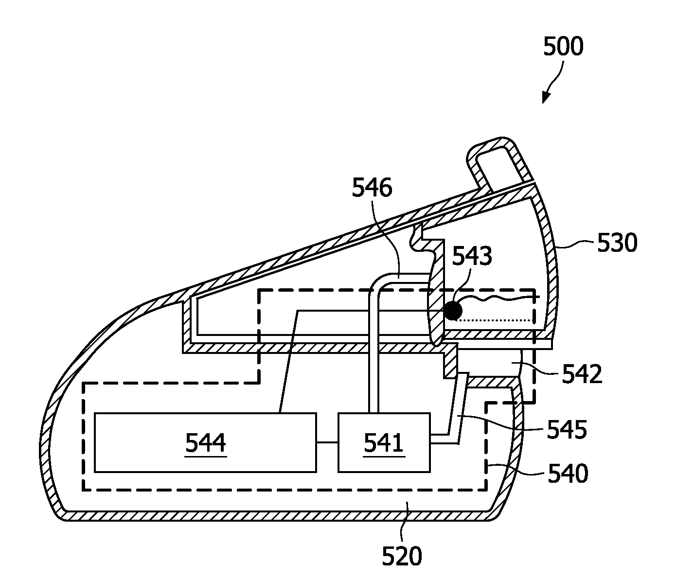
A steaming system (100) comprises a steam generator (120), a removable water tank (130) for holding and supplying water to the steam generator (120); and a dosing device (140) for supplying an amount of a water treatment agent to the water tank (130). The dosing device is configured to be triggered by a movement of the water tank (130) relative to the steam generator (120).

Description

FIELD OF INVENTION[0001]This invention relates to a steaming system, more particularly to a steaming system used for ironing devices.BACKGROUND OF THE INVENTION[0002]A steam generator of a steaming system is typically filled with tap water which normally contains various gases as well as salts. Salts which are customarily found in tap water include sodium bicarbonate, sodium sulfate and magnesium bicarbonate. The percentage of sodium and magnesium salts determines the hardness of water. The heating entails decomposition of water into its constituents, and such constituents, especially carbonates, deposit on the adjacent surfaces in the form of scale. The scale is an insulator of heat so that the energy requirements of the steam generator increase as the thickness of the scale increases. The scale can be carried over with the steam to the outlet of the steam generator, causing the clogging of steam vents and staining users' articles. The steam rate can also be reduced due to the clog...

Claims


Application Information

Patent Timeline
Patent Type & Authority Applications(United States)
IPC IPC(8): D06F75/14
CPCF22B1/284D06F75/14
Inventor JI, LANYINGONG, KENG CHYE JIMMYKASEVAN, ASOK KUMARJIANG, YONG
Owner KONINKLIJKE PHILIPS ELECTRONICS NV
Learn More