
Thermoelectric conversion elements, thermoelectric conversion modules and a production method of the thermoelectric conversion modules

a technology of thermoelectric conversion modules and conversion elements, which is applied in the manufacture/treatment of thermoelectric devices, thermoelectric device junction materials, electrical apparatuses, etc., can solve the problems of low productivity, high cost, and difficult assembly process, and achieves improved electric conductivity, lowering thermal conductivity, and high thermal conductivity.

Inactive Publication Date: 2010-04-22
ISHIKAWA PREFECTURAL GOVERNMENT +2
View PDF8 Cites 16 Cited by
  • Summary
  • Abstract
  • Description
  • Claims
  • Application Information

AI Technical Summary

Benefits of technology

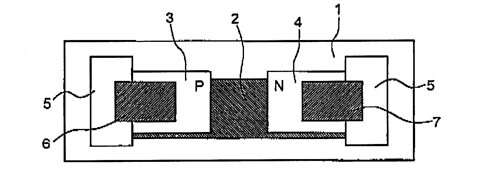
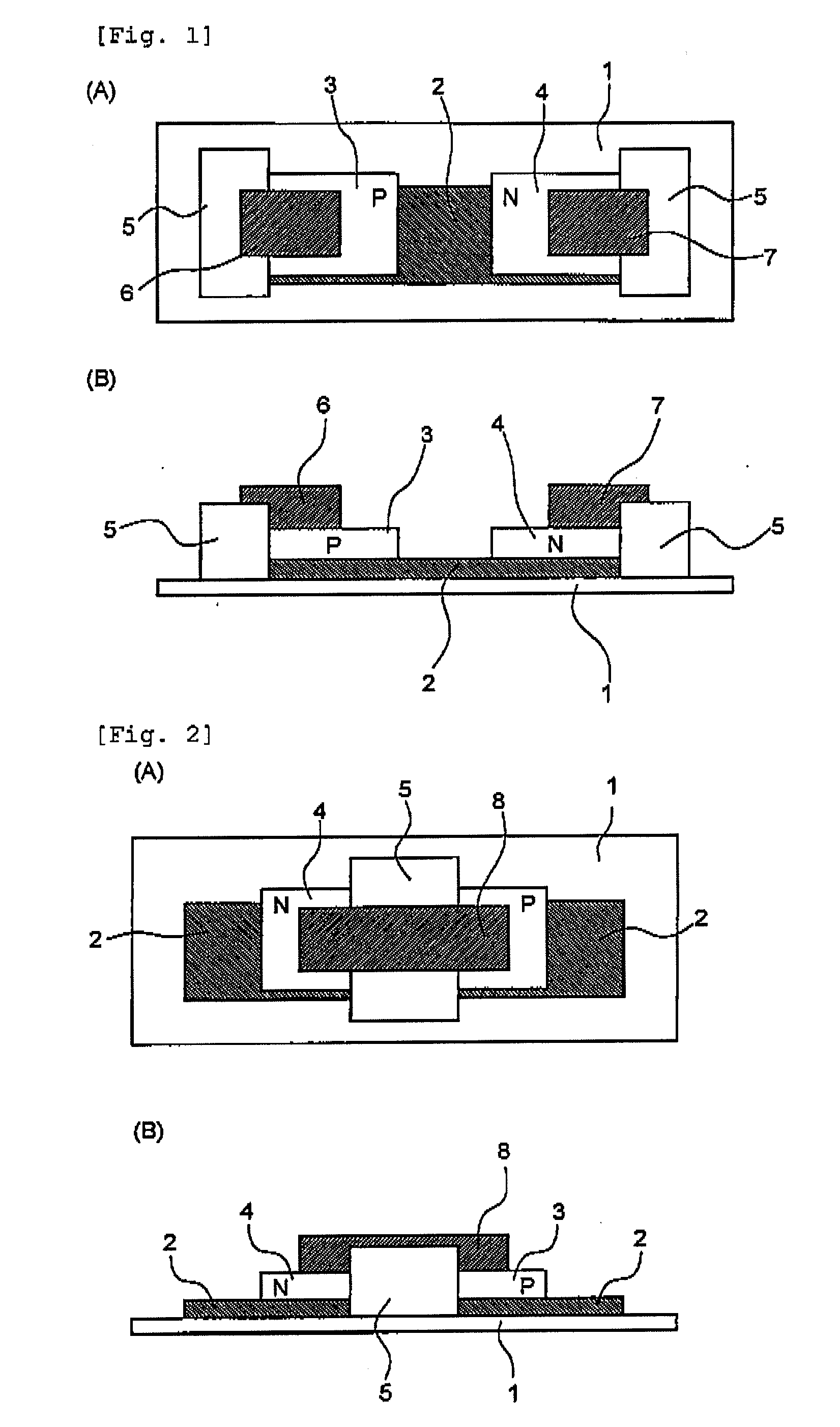
The present invention provides a solution to the problems of conventional thermoelectric conversion elements, such as troublesome production steps and difficulty in making a thin structure. The invention provides a thermoelectric conversion element that has a thin-film structure and is excellent in thermal stability and chemical durability at low cost. The invention also provides a production method for the thermoelectric conversion module. The technical effects of the invention include a simplified production process and a more compact and efficient thermoelectric conversion module.

Problems solved by technology

Furthermore, the assembling process is difficult since the thermoelectric elements are produced by slicing to mount to the thermoelectric module with a pair of the pair-type n- and p-type thermoelectric segments.
Thus, productivity is low and the cost is high.
However, the process is very expensive and not very well suited for mass production.

Method used


Image

  • Thermoelectric conversion elements, thermoelectric conversion modules and a production method of the thermoelectric conversion modules
  • Thermoelectric conversion elements, thermoelectric conversion modules and a production method of the thermoelectric conversion modules
  • Thermoelectric conversion elements, thermoelectric conversion modules and a production method of the thermoelectric conversion modules

Examples


examples

[0059]The production process of the thermoelectric conversion module in the embodiments of the present invention is described below with reference to FIG. 4(A) to (D).

[0060]A thermoelectric semiconductor element was prepared for examples. A calcium-cobalt oxide thermoelectric material (Ca2.7La0.3Co4O9) as a material for p-type thermoelectric conversion elements was prepared as follows: Calcium carbonate (CaCO3), lanthanum oxide (La2O3) and cobalt oxide (Co3O2) were measured to make determined compositions (Ca2.7La0.3Co4O9). After mixing and press molding the compounds, the mixture was calcined in the air flow (200 ml / min.) at 780° C. for two hours and pulverized. After being subjected to pulverizing, mixing and press-molding again, the resultant was calcined in the air flow (200 ml / min.) at 800° C. for three hours and pulverized. The resultant was press molded (at the pressure of 200 MPa) by CIP (cold isostatic press) and sintered in the air at 870° C. for ten hours.

[0061]A calcium-...


PUM


Abstract

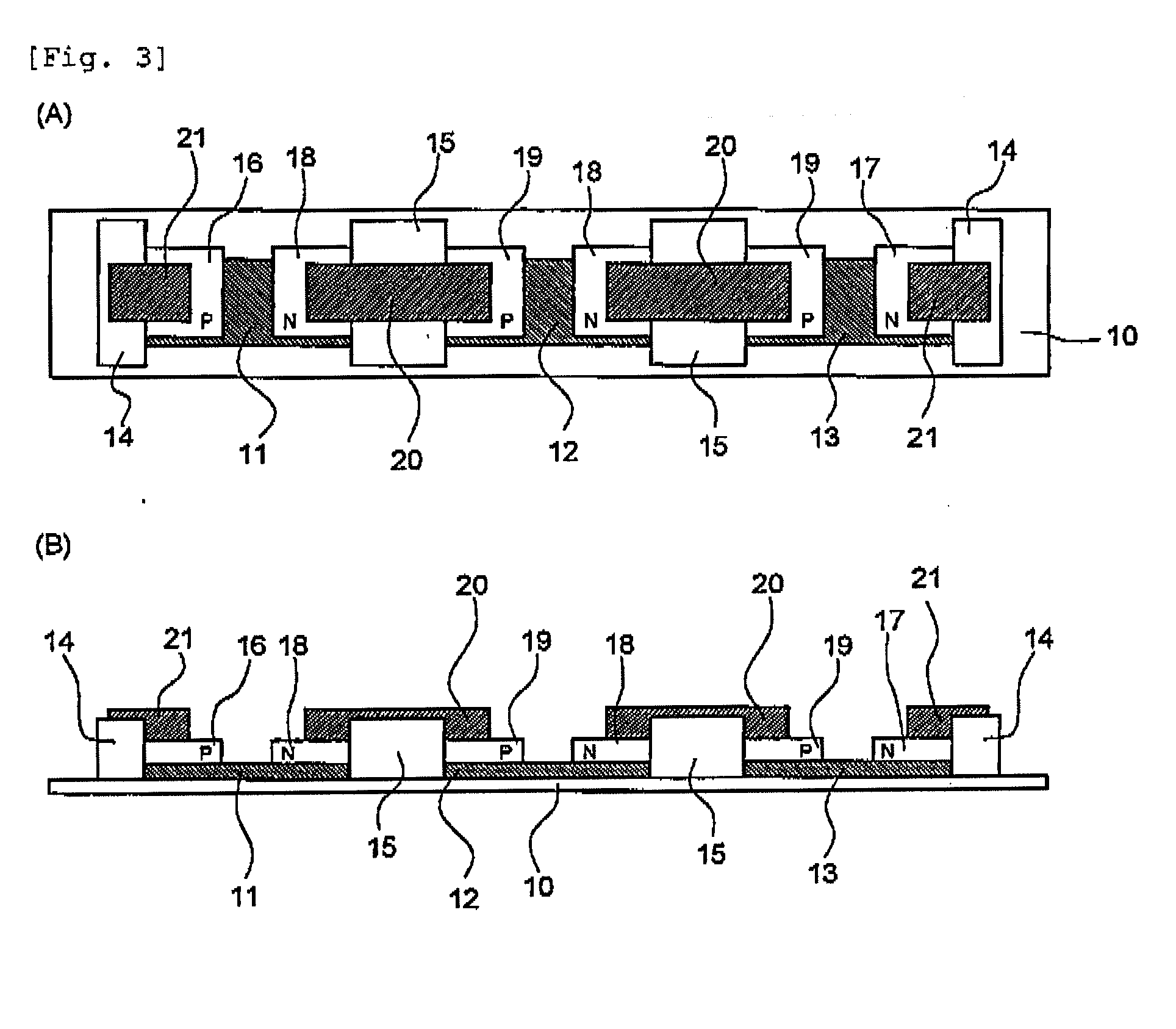
The present invention provides a thermoelectric conversion module, comprising plural first electrode films (11, 12, 13) formed apart from each other on the top surface of an insulating body (10), plural p- and n-type thermoelectric semiconductor element films (16, 19) and (17, 18) formed thereon, which are arranged apart from each other so that p- and n-type thermoelectric semiconductor element films alternate with each other, and second electrode films (20) connecting p-type thermoelectric semiconductor element film (19) and n-type thermoelectric semiconductor element film (18) over the gaps between the first electrode films; and a terminal electrode is connected to each of the p-and n-type thermoelectric semiconductor element film (16, 17) at the end; and a production method thereof. The thermoelectric conversion module of the present invention, which can be produced at a low cost using thermoelectric conversion elements having a thin-film structure, is excellent in thermal stability and chemical durability and enables to secure high thermoelectric conversion efficiency.

Description

CROSS-REFERENCE TO RELATED APPLICATIONS[0001]This application incorporates complete content disclosed by the specification, drawings and abstract of Japanese Patent Application No. 2007-109210 filed on Apr. 18, 2007.TECHNICAL FIELD[0002]The present invention relates to thermoelectric conversion elements which convert a temperature differential between the front-side and the back-side of a substance into electrical energy and vice versa, thermoelectric conversion modules using the thermoelectric conversion elements and a production method thereof.BACKGROUND ART[0003]Conventionally, a thermoelectric conversion system has been in practical use, which system converts thermal energy into electrical energy and vice versa by means of Seebeck effect and Peltier effect. In the thermoelectric conversion system, p- and n-type thermoelectric conversion semiconductors are used which are referred to as thermoelectric conversion elements. Generally, these elements generate small voltage per elemen...

Claims


Application Information

Patent Timeline
Patent Type & Authority Applications(United States)
IPC IPC(8): H01L35/00H10N10/00
CPCH01L35/22H01L35/34H01L35/32H10N10/855H10N10/01H10N10/17
Inventor TOYODA, TAKESHINAKAMURA, SHIZUOTAKIMOTO, MIKIOKIDANI, NAOKIKAMEI, HIROSHIMIZUKOSHI, HIROHARUMASUI, MEGUMI
Owner ISHIKAWA PREFECTURAL GOVERNMENT
Learn More