Dynamoelectric machine

a dynamoelectric machine and rotor technology, applied in the direction of magnetic circuit rotating parts, magnetic circuit shape/form/construction, windings, etc., can solve the problems of increasing the inertia of the rotor, and invariably increasing the size of the alternator, so as to facilitate the holding reduce the moment of inertia that accompany the disposition of the permanent magnet, and reduce the centrifugal force tha

Active Publication Date: 2010-04-22
MITSUBISHI ELECTRIC CORP
View PDF9 Cites 15 Cited by
  • Summary
  • Abstract
  • Description
  • Claims
  • Application Information

AI Technical Summary

Benefits of technology

[0040]According to the present invention, permanent magnets are held near yoke portions. Thus, because displacement of the claw-shaped magnetic poles that results from centrifugal forces and thermal expansion will not affect the permanent magnets, the occurrence of cracking or chipping of the permanent magnets that results from the displacement of the claw-shaped magnetic pole portions is suppressed, and holding of the permanent magnets is facilitated. Because the permanent magnets are positioned radially inside the claw-shaped magnetic pole portions, increases in moment of inertia that accompany disposition of the permanent magnets are reduced. In addition, centrifugal forces that act on the permanent magnets are also reduced, facilitating holding of the permanent magnets.
[0041]Because the permanent magnets are disposed so as to face inner circumferential surfaces near tip ends of the claw-shaped magnetic pole portions, the permanent magnets are positioned radially inside the claw-shaped magnetic pole portions and are not heated by induction directly due to stator slot harmonics, enabling thermal demagnetization to be prevented.
[0042]In addition, because the permanent magnets are magnetically oriented in a reverse direction to the orientation of the magnetic field produced by the field coil, the magnetic field circuits formed by the permanent magnets are closed inside the rotor, suppressing the occurrence of induced voltages during no-load de-energization.

Problems solved by technology

If attempts are made to answer these demands within the scope of conventional design, the alternators are invariably increased in size.
Increases in alternator size are undesirable since the weight of and space occupied by such alternators is increased.
Increases in alternator size are also known to give rise to new problems such as leading to increased rotor inertia, and engine speed fluctuations and alternator inertial torque interacting and leading to belt vibration and slippage.
In other words, if the two are placed in point contact, local stresses may be concentrated on the magnets, and the magnets may be damaged.
Because raising magnet processing precision is difficult in mass-produced products, it is also possible to consider means for ensuring external shape precision of the magnets using SUS plates or resin molds instead, but these lead to enormous costs.
Realistically, ensuring such parts precision increases costs significantly during mass production of rotors.
In addition, even if static shape precision is adapted in this manner, magnet holding in automotive alternators is still difficult.
However, the above-mentioned conventional improved magnet holding construction has problems of induced voltage during no-load de-energization.
However, since automotive engines have a variable speed range of approximately 1:10, if, for example, the maximum engine speed is ten times that of idling, the one- or two-volt induced voltages from the magnets may exceed the system voltage of the vehicle and have adverse effects on other on-board equipment.
One problem is that when the direction of flow of the current becomes bidirectional instead of unidirectional, a bidirectional circuit that incorporates an H-bridge is required instead of simple chopper control, increasing the number of components, and raising product costs.
Furthermore, unlike a normal field, it is necessary to start this reverse field swiftly in response to increases in engine speed, but since a coil that has a high impedance of several hundred turns is used so as to be able to control the field using a small current of approximately several amperes, it is currently difficult to make the reverse field current flow instantaneously.
If the number of field turns is reduced in order to avoid this, new problems arise such as the electric current value of the control power source itself also being increased, increasing control element capacity, and raising product costs.
One problem is that if even a portion of a magnet is heated by induction and reaches a high temperature locally, heat will transfer to the entire magnet, and the magnet will be thermally demagnetized.
Portions of the magnets or magnet holding metal fittings are also exposed on the rotor surface facing the stator in the conventional improved magnet holding construction, making thermal demagnetization of the magnets similarly problematic.

Method used


Image

  • Dynamoelectric machine
  • Dynamoelectric machine
  • Dynamoelectric machine

Examples


embodiment 1

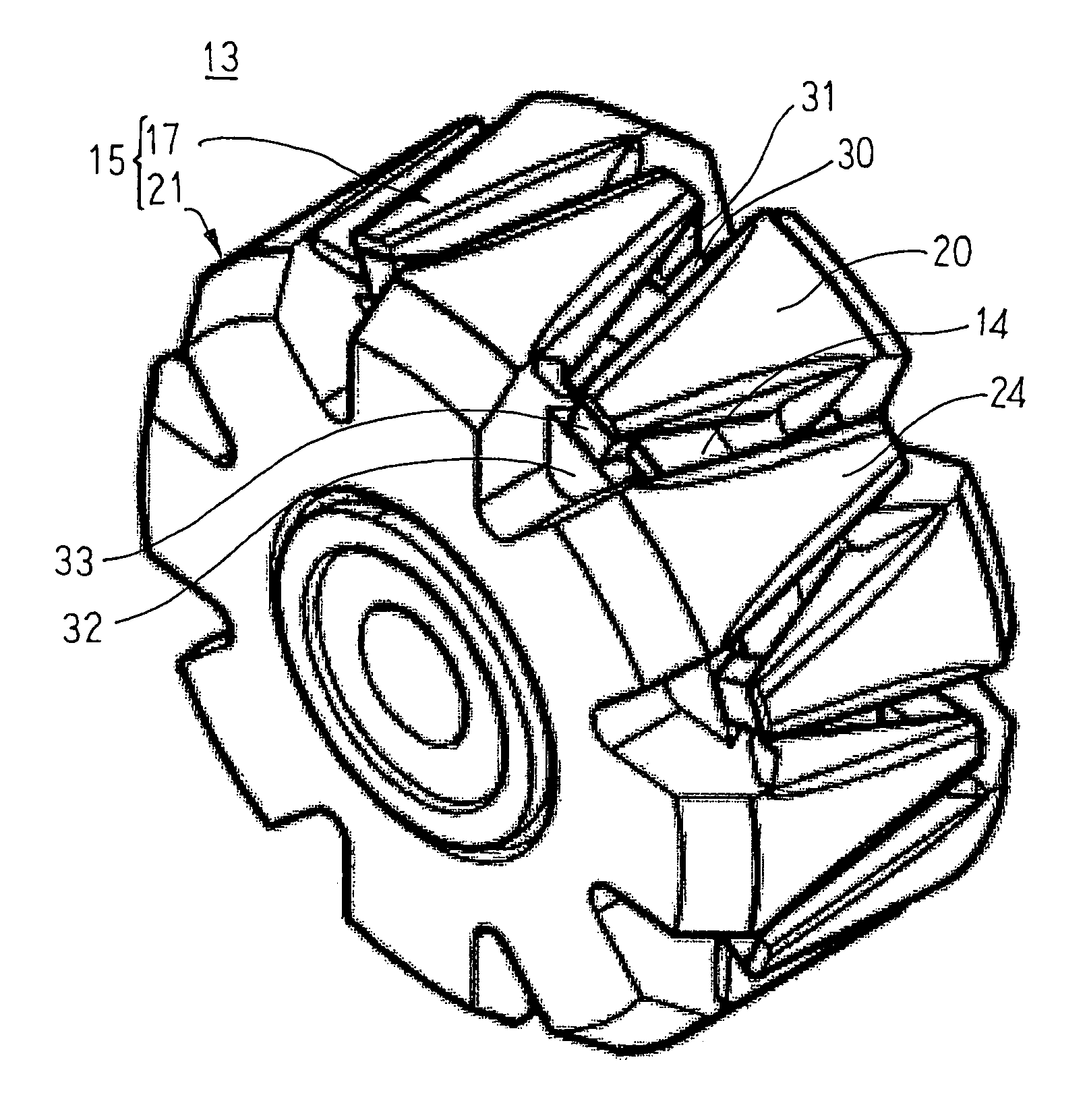
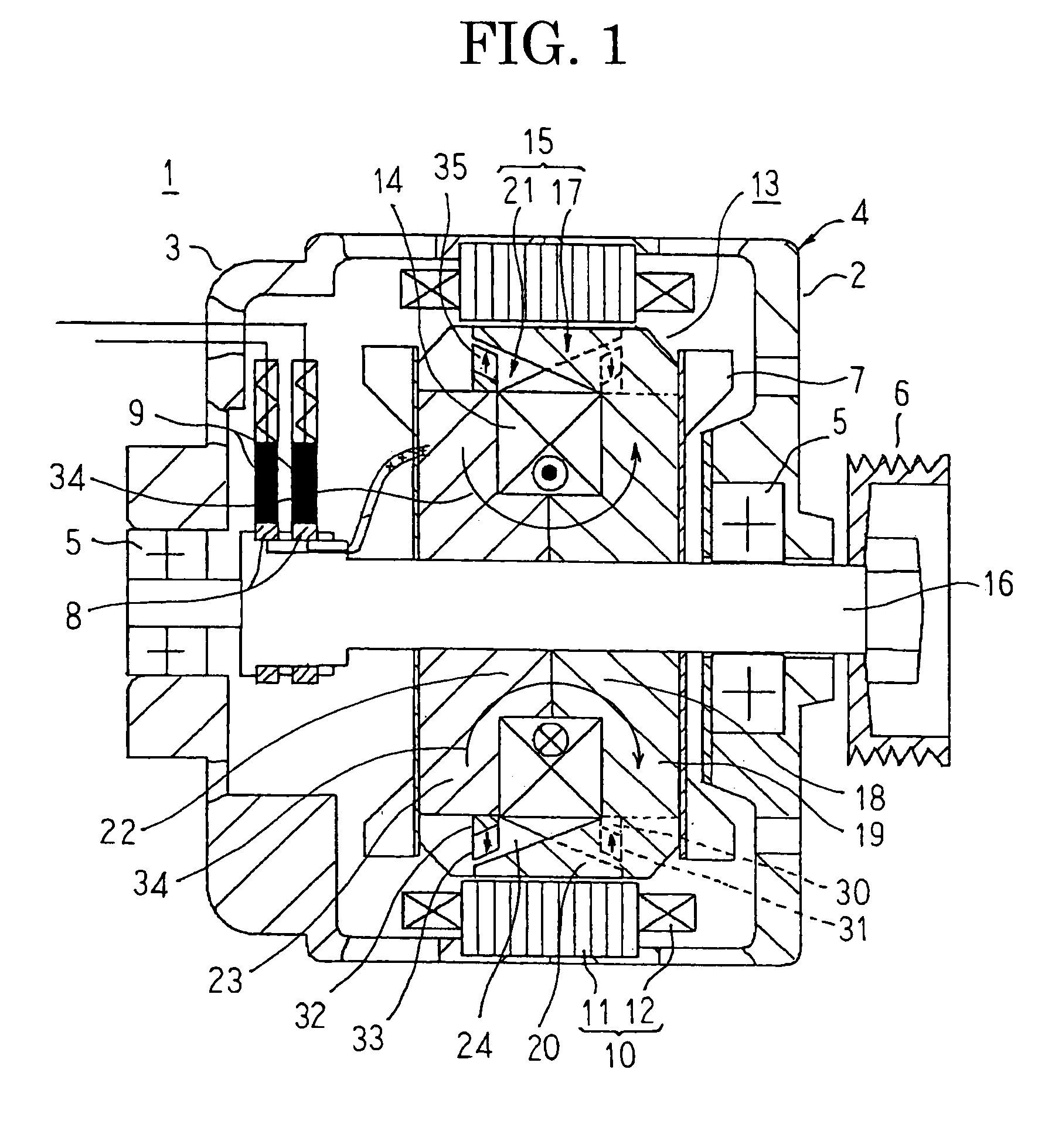
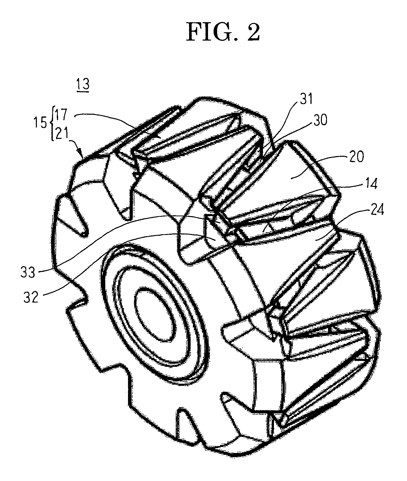
[0059]FIG. 1 is a cross section that schematically shows an automotive alternator according to Embodiment 1 of the present invention, FIG. 2 is a perspective that shows a rotor that can be used in the automotive alternator according to Embodiment 1 of the present invention, and FIGS. 3 and 4 are respective schematic diagrams for explaining flow of magnetic flux in the automotive alternator according to Embodiment 1 of the present invention.

[0060]In FIGS. 1 and 2, an automotive alternator 1 includes: a case 4 that is constituted by a front bracket 2 and a rear bracket 3 that are each made of aluminum so as to have an approximate cup shape; a rotor 13 that is rotatably disposed inside the case 4 such that a shaft 16 is supported by means of bearings 5 in the case 4; a pulley 6 that is fixed to an end portion of the shaft 16 that projects outward at a front end of the case 4; fans 7 that are fixed to two end surfaces in an axial direction of the rotor 13; a stator 10 that is fixed to t...

embodiment 2

[0090]In Embodiment 1 above, the direction of magnetization 35 of the first and second permanent magnets 31 and 33 is oriented radially, but in Embodiment 2, a direction of magnetization 35 of first and second permanent magnets 31 and 33 is inclined toward a field coil 14 relative to a radial direction.

[0091]Moreover, the rest of the configuration is configured in a similar manner to Embodiment 1 above.

[0092]In FIG. 7, the first permanent magnets 31 are formed so as to have parallelogrammatic cross sections, and are fixed to upper surfaces of the first magnet seats 30 so as to face the inner circumferential surfaces of the tip end portions of the second claw-shaped magnetic pole portions 24 using an adhesive, etc., so as to be magnetically connected. The upper surfaces of the first permanent magnets 31 are approximately parallel to the inner circumferential surfaces of the second claw-shaped magnetic pole portions 24 so as to have a predetermined clearance. The directions of magneti...

embodiment 3

[0117]FIG. 13 is an end elevation that shows a rotor that can be used in an automotive alternator according to Embodiment 3 of the present invention.

[0118]In FIG. 13, tapered grooves 50 that function as interfitting recess portions are disposed so as to extend axially on outer circumferential surfaces of a second yoke portion 23 that are positioned between second claw-shaped magnetic pole portions 24 of a second pole core body 21 so as to have internal shapes in which two side walls slant inward. Second permanent magnets 33 are also formed so as to have trapezoidal cross sections that fit together with the tapered grooves 50. The second permanent magnets 33 are press-fitted into the tapered grooves 50 from axially outside, and held.

[0119]Although not shown, tapered grooves 50 are also disposed so as to extend axially on outer circumferential surfaces of a first yoke portion 19 that are positioned between first claw-shaped magnetic pole portions 20 of a first pole core body 17. First...


PUM


Abstract

A dynamoelectric machine including first and second permanent magnets held by first and second magnet seats on first and second yoke portions so as to face inner circumferential surfaces of tip end portions of first and second claw-shaped magnetic pole portions. The first and second permanent magnets are magnetically oriented in a reverse direction to orientation of a magnetic field that the field coil produces. The dynamoelectric machine enables permanent magnet holding reliability to be increased, induced voltage during no-load de-energization to be suppressed, and thermal demagnetization of magnets due to high-frequency magnetic fields that are induced by stator slots to be avoided.

Description

TECHNICAL FIELD[0001]The present invention relates to a dynamoelectric machine such as an automotive alternator, etc., and particularly relates to a Lundell rotor structure to which permanent magnets are mounted.BACKGROUND ART[0002]Automotive alternators that use Lundell rotors have been used in automobiles for decades. Loads from electrical equipment that is mounted due to environmental issues have been increasing rapidly in recent years, and further increases in generated power are being sought from Lundell rotors.[0003]If attempts are made to answer these demands within the scope of conventional design, the alternators are invariably increased in size. Increases in alternator size are undesirable since the weight of and space occupied by such alternators is increased. Increases in alternator size are also known to give rise to new problems such as leading to increased rotor inertia, and engine speed fluctuations and alternator inertial torque interacting and leading to belt vibra...

Claims


Application Information

Patent Timeline
Patent Type & Authority Applications(United States)
IPC IPC(8): H02K21/04H02K1/27
CPCH02K21/044
Inventor INOUE, MASAYASHINKAWA, KANJIMORITA, MASAOKOMETANI, HARUYUKIYOSHIZAWA, TOSHIYUKIHAZEYAMA, MORIYUKIITO, KEIICHIMORI, TAKESHIAKITA, HIROYUKIMIYAMOTO, YOSHINORINISHIMURA, SHINJI
Owner MITSUBISHI ELECTRIC CORP
Why Eureka
Try Eureka