Lighting device

a technology of light source and fan, which is applied in the direction of semiconductor devices for light sources, semiconductor/solid-state device details, lighting and heating apparatus, etc., can solve the problems of reducing the cooling effect of the fan, affecting the cooling effect, and consuming a lot of energy, so as to achieve less energy input, improve the cooling effect, and more cooling

Active Publication Date: 2010-04-22
SIGNIFY HLDG BV
View PDF8 Cites 60 Cited by
  • Summary
  • Abstract
  • Description
  • Claims
  • Application Information

AI Technical Summary

Benefits of technology

[0007]Experiments have shown that this cooling mode is significantly more effective than the conventional cooling mode using an electric fan. In practice, the vibrating membrane cooling system was found to produce two to three times more cooling with two-thirds less energy input than with a conventional fan. The system is even more efficient when the vibrating membrane cooling system is embodied as a resonance cooling system. The vibrating membrane cooling system is simple and has no friction parts susceptible to wear, while the synthetic jet module (=vibrating membrane cooling system) resembles a tiny stereo speaker in which a diaphragm is mounted within a cavity (=vibrating membrane chamber) that has one or more orifices (=cooling openings). The cooling system may comprise one or more synthetic jet modules and heat sinks, which modules can be located above, below or next to the light source. The cooling system is usable for cooling both the light source and/or other parts of the lighting device, for example, the driver means (=electronic circuit).
[0008]An embodiment of the lighting device is characterized in that at least one cooling opening has at least two, preferably at least four orifices, and in that said cooling orifices are arranged alongside the contour of the heat sink. The cooling device thus creates a cooling pattern that has a shape similar to the contour of the heat sink, with the result that the heat sink is flushed with a fluid flow. A major part, for example, more than 50%, preferably more than 70%, more preferably more than 85% of the contour of the heat sink, which may be an inner contour, an outer contour or both an inner and an outer contour, is exposed to a fluid flow created by the cooling device. The more the contour is exposed, the better the cooling. The fluid may be a gas or a liquid. If the fluid is a gas, it is preferably air. Four openings, or orifices, allow creation of a three-dimensional arrangement of the openings and thus effective cooling of a three-dimensional heat sink, for example, by providing two cooling openings at its outer side flushing the outer contour and two other cooling openings at its inner side flushing the inner contour. If the contour is compliant with a curved surface/plane, it is also possible to substantially totally flush, for example, the outer side of the heat sink with flowing fluid by way of the three-dimensional arrangement of the cooling openings.
[0009]A further embodiment of the lighting device is characterized in that the light source comprises optical means for collimating and directing light originating from the light source during operation, the contour of the heat sink having a shape which is similar to that of the optical means. It is thus realized that the

Problems solved by technology

The known lighting device has the drawback that use of the fan for the purpose of cooling has a number of limitations.
For example, much of the circulated gas, for example, air bypasses the heat sink and do

Method used


Image

  • Lighting device
  • Lighting device
  • Lighting device

Examples


first embodiment

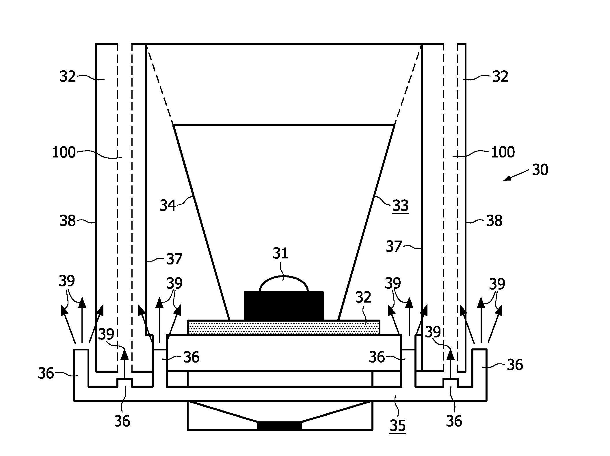
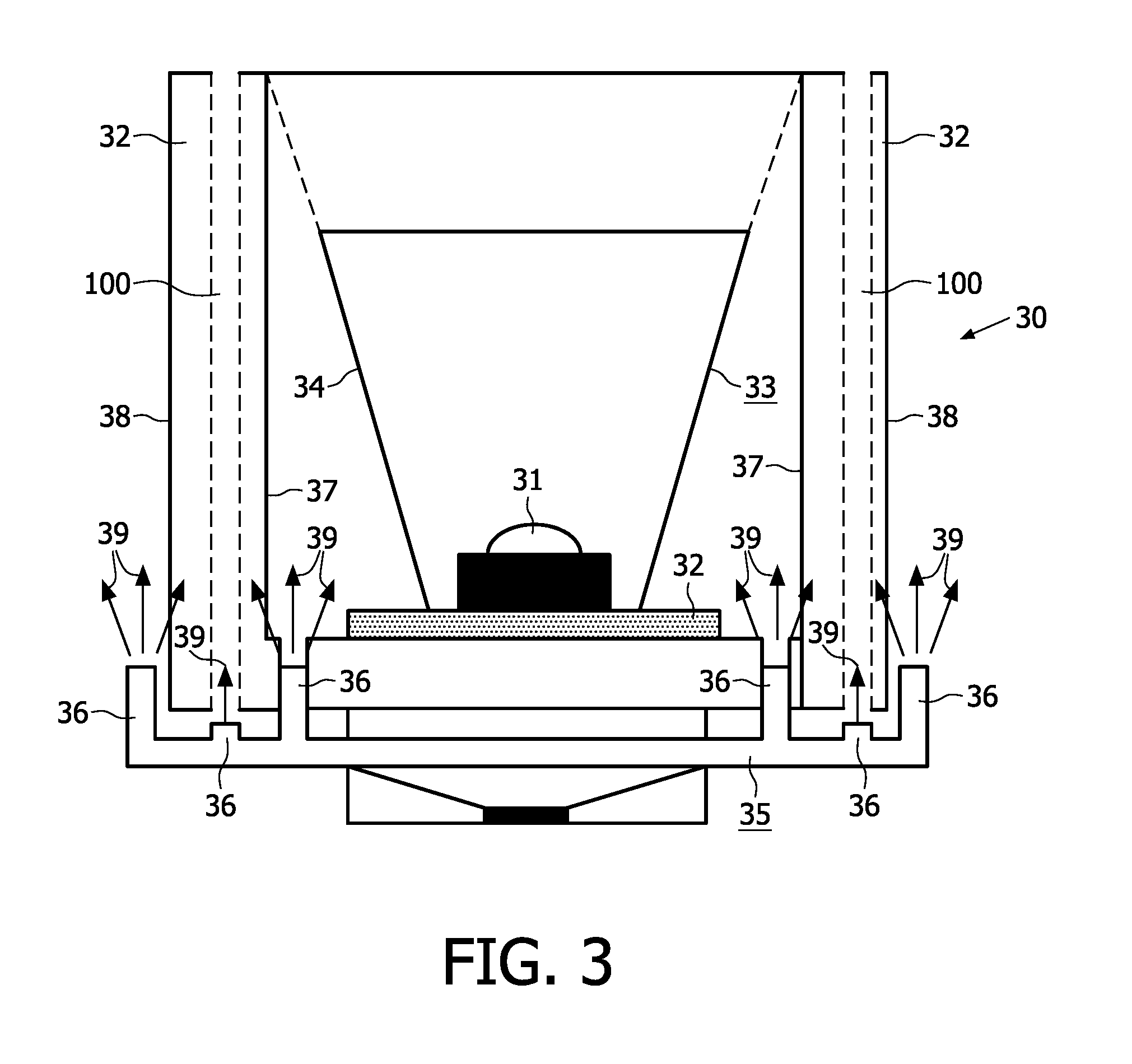
[0029]FIG. 3 is a schematic view of a lighting device 30 according to the invention. The lighting device comprises a light source 31, in the Figure a compact high-pressure mercury vapor discharge lamp, for example, a UHP lamp. The light source is mounted on a heat sink 32 and further comprises optical means 33, in the Figure a parabolic reflector 33. The heat sink substantially has a shape which is similar to an outer contour 34 of the reflector. A vibrating membrane cooling device 35, in the Figure a resonant cooling system analogous to the one shown in FIG. 2, is provided adjacent the heat sink. The device 35 has six orifices 36 that flush the heat sink with a sequence of fluid pulses 39 which, once out of the orifice, become a turbulent fluid flow, both on its inner 37 and outer contour / side 38. Furthermore, the heat sink comprises channels 100 into which fluid pulses 39 are supplied via respective cooling openings 36. As a result of the overall cooling of the heat sink, the ligh...

second embodiment

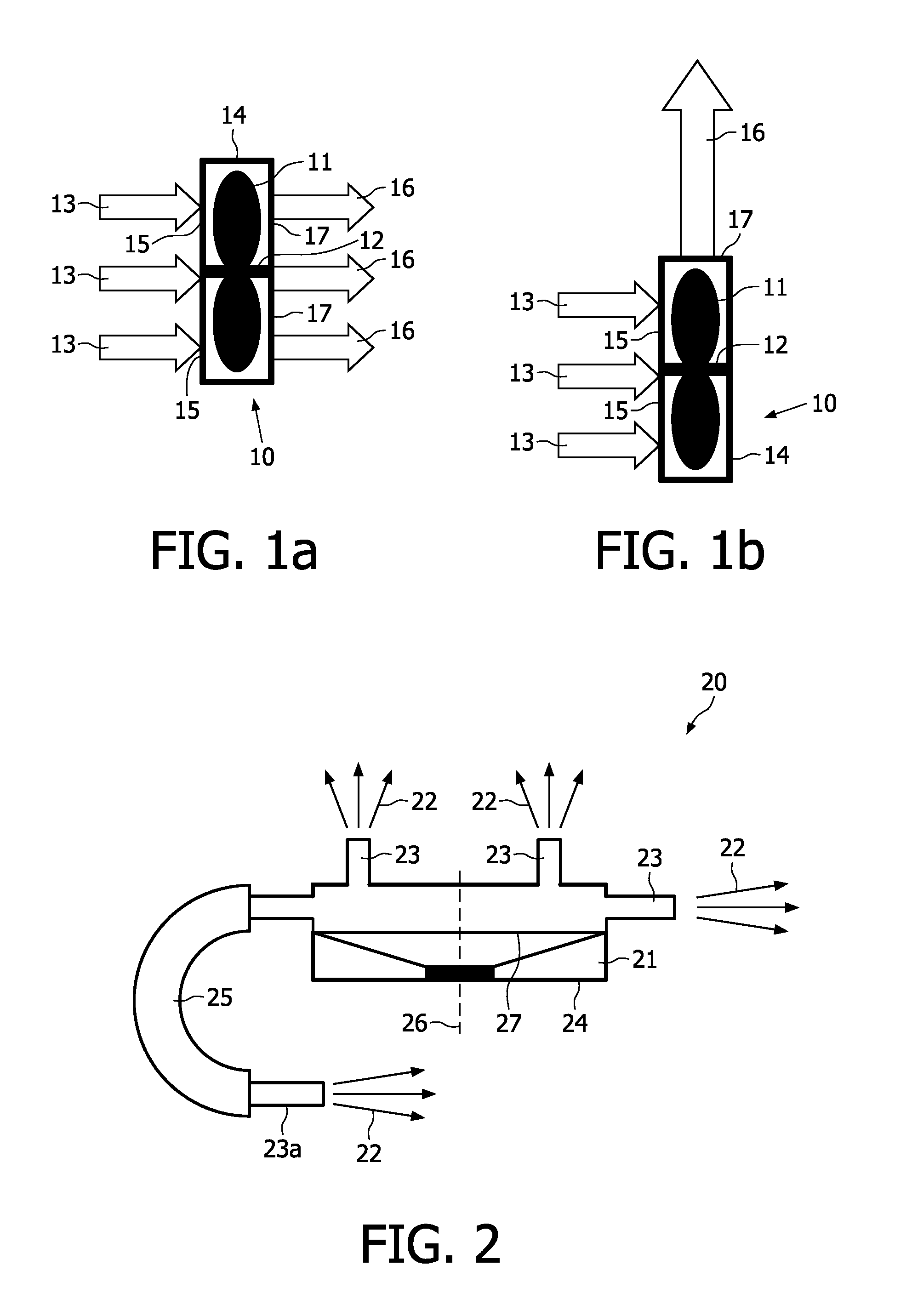
[0030]FIG. 4 is a schematic view of a lighting device 30 according to the invention. In this embodiment, the light source, in the Figure a part 42 comprising a white LED 31, optical means 33 and heat sink 32 is remote from a chamber 40 which forms part of the vibrating membrane cooling device 35. The fluid pulse sequence, in the Figure the fluid is air, is generated in the chamber and transported via an air pulse conductor 41 to the heat sink which is effectively cooled thereby. In this embodiment, the chamber has only one orifice 43. In an alternative arrangement (not shown), the remote part 42 is suspended via the air pulse conductor to a (false) ceiling and the chamber is tucked away in the ceiling or behind the false ceiling.

third embodiment

[0031]FIG. 5 is a diagrammatic view of a lighting device according to the invention, in which the chamber 40 is positioned inside the heat sink 32. This has the advantage that the lighting device takes up even less space and allows an aesthetic design. In this embodiment, there are three orifices / cooling openings 43.


PUM


Abstract

The invention relates to a lighting device comprising a light source (31) which is mounted on a heat sink (32) having an outer contour (34). Furthermore, it comprises a cooling device (35) for dynamically cooling the light source via cooling of the heat sink by means of a fluid flowing alongside the contour of the heat sink, the cooling device having one or a plurality of cooling openings (36, 43). The cooling device is a vibrating membrane cooling system for generating a sequence of fluid pulses (39). The cooling openings are arranged alongside the heat sink. The light source comprises optical means (33) for collimating and directing light originating from the light source during operation, while the contour of the heat sink has a shape similar to that of the optical means.

Description

FIELD OF THE INVENTION[0001]The invention relates to a lighting device.BACKGROUND OF THE INVENTION[0002]Such a lighting device is known from GB2420172A. The known lighting device comprises a light source which is mounted on a heat sink. The heat sink has a contour. It has also a cooling device which is an electric fan for dynamically cooling the light source via cooling of the heat sink by means of a gas flow. The known lighting device has the drawback that use of the fan for the purpose of cooling has a number of limitations. For example, much of the circulated gas, for example, air bypasses the heat sink and does not mix well with the thermal boundary layer that is formed on the cooling fins of the heat sink. A fan placed directly opposite or over said heat sink has “dead areas” where its motor assemblies block the airflow, causing, for example, a turbulent gas flow. Furthermore, a fan uses relatively much energy, creates audible noise and takes up relatively much space.OBJECT AND...

Claims


Application Information

Patent Timeline
IPC IPC(8): H01J61/52
CPCF04D33/00F04F7/00F21V29/02F21Y2101/02F21V29/63H01L2924/0002H01L23/467H01L2924/00F21Y2115/10
Inventor MARINUS, ANTONIUS ADRIANUS MARIATREURNIET, THEODOOR CORNELISVAN AS, MARCOVERHOEVEN, MARK JOHANNES ANTONIUS
Owner SIGNIFY HLDG BV
Why Eureka
Try Eureka