Piezoelectric element, liquid ejecting head, and liquid ejecting apparatus
- Summary
- Abstract
- Description
- Claims
- Application Information
AI Technical Summary
Benefits of technology
Problems solved by technology
Method used
Image

Examples
first embodiment
1. First Embodiment
1.1. Piezoelectric Element
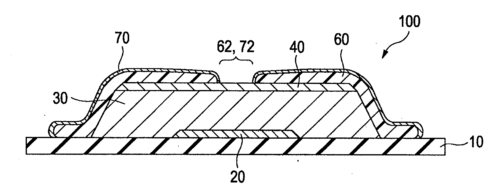
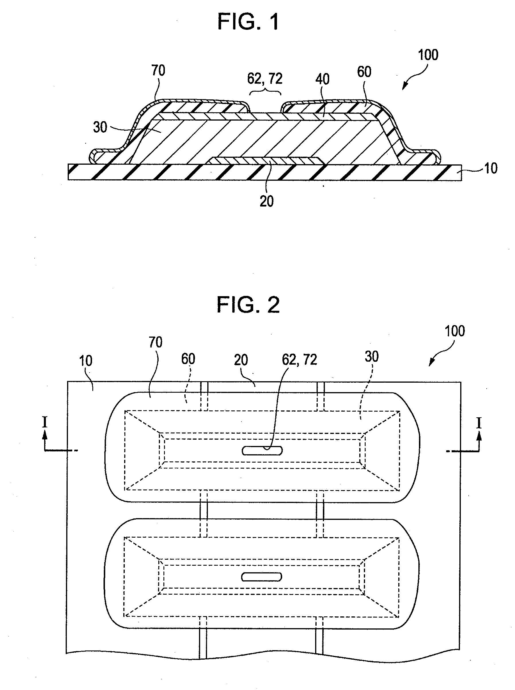
[0046]FIGS. 1 and 2 are a cross-sectional diagram and a plan view, respectively, of a piezoelectric element 100 according to the first embodiment of the present invention. The piezoelectric element 100 has a substrate 10, a lower electrode 20, a piezoelectric layer 30, an upper electrode 40, protection layers 60, and self-organized monomolecular films 70.
[0047]The substrate 10 gives mechanical outputs when the piezoelectric element 100 operates. Configured to have a diaphragm or the like, the substrate 10 can be a moving part of a liquid ejecting head or a part of walls of a pressure generator or the like. The substrate 10 has a thickness appropriately chosen on the basis of the modulus of elasticity of its material and other factors. When the substrate 10 is a diaphragm used in a liquid ejecting head, its thickness can be in the range of 200 to 2000 nm. A thickness of the substrate 10 falling below 200 nm would cause difficulties in givi...
second embodiment
2. Second Embodiment
2.1. Piezoelectric Element
[0076]FIG. 9 is a cross-sectional diagram of a piezoelectric element 200 according to the second embodiment of the present invention. The piezoelectric element 200 has the same configuration as the piezoelectric element 100 according to the first embodiment of the present invention, except for the absence of the protection layers 60. Thus, like numbers reference like members in the piezoelectric element 100 for simplicity of description.
[0077]The piezoelectric element 200 according to this embodiment has a substrate 10, a lower electrode 20, a piezoelectric layer 30, an upper electrode 40, and self-organized monomolecular films 70.
[0078]As described in the first embodiment, the self-organized monomolecular films 70 have an excellent ability to block moisture. The piezoelectric element 200 has such self-organized monomolecular films 70 on the lateral sides of the piezoelectric layer 30 for the prevention of external moisture from entering...
third embodiment
3. Third Embodiment
3.1. Piezoelectric Element
[0080]FIG. 10 is a cross-sectional diagram of a piezoelectric element 300 according to the third embodiment of the present invention. The piezoelectric element 300 has the same configuration as the piezoelectric element 100 according to the first embodiment of the present invention, except for the absence of the self-organized monomolecular films 70 and the presence of parylene resin layers 80 used instead of the protection layers 60. Thus, like numbers reference like members in the piezoelectric element 100 for simplicity of description.
[0081]The piezoelectric element 300 according to this embodiment has a substrate 10, a lower electrode 20, a piezoelectric layer 30, an upper electrode 40, and parylene resin layers 80.
[0082]As described in the first embodiment, parylene resins have sufficiently small Young's modulus (≦1×10¹⁰ Pa) and excellent performance in blocking foreign matter such as moisture, hydrogen molecules, and reducing gases....
PUM
 Abstract
Description
Claims
Application Information
 - Generate Ideas
- Intellectual Property
- Life Sciences
- Materials
- Tech Scout
- Unparalleled Data Quality
- Higher Quality Content
- 60% Fewer Hallucinations
Browse by: Latest US Patents, China's latest patents, Technical Efficacy Thesaurus, Application Domain, Technology Topic, Popular Technical Reports.
© 2025 PatSnap. All rights reserved.Legal|Privacy policy|Modern Slavery Act Transparency Statement|Sitemap|About US| Contact US: help@patsnap.com