
Linear compressor

a compressor and linear technology, applied in the direction of machines/engines, positive displacement liquid engines, pumping, etc., can solve the problems of reducing the stability of linear compressors, unable to use mechanical springs, and affecting the operation of linear compressors, etc., to achieve stab operation, reduce noise and vibration, and simplify the design

Inactive Publication Date: 2010-04-22
LG ELECTRONICS INC
View PDF20 Cites 42 Cited by
  • Summary
  • Abstract
  • Description
  • Claims
  • Application Information

AI Technical Summary

Benefits of technology

[0021]According to the present invention, in a linear compressor, a third elastic body having both ends supported on a stationary part and a moving part respectively and applying a restoring force so that the moving part can operate in a resonance condition can have a positive number as an spring constant.
[0022]In addition, according to the present invention, in a linear compressor, an operating frequency is regulated so that a third elastic body can have a positive number as an spring constant.
[0023]Moreover, according to the present invention, in a linear compressor, a transfer force transferred to a shell is offset to reduce noise and vibration.
[0024]Further, according to the present invention, in a linear compressor, as an spring constant of an elastic body provided so that a moving part can operate in a resonance condition is a positive number, the elastic body can be implemented with a mechanical spring.
[0025]Furthermore, according to the present invention, in a linear compressor, a third elastic body can be implemented with a mechanical spring. As compared with a case where the third elastic body is implemented with a gas spring, it simplifies the design, rigidity regulation and control.
[0026]Still furthermore, according to the present invention, a transfer force transferred to a shell is offset, so that a linear compressor can operate stably.

Problems solved by technology

The vibration of the shell is disadvantageous because it degrades the stability of the linear compressor and muses noise.
It is thus impossible to use a mechanical spring which is the most widely-used and easily-controllable elastic body.

Method used


Image

  • Linear compressor
  • Linear compressor
  • Linear compressor

Examples


Embodiment Construction

[0031]Hereinafter, a linear compressor according to the present invention will be described in detail with reference to the accompanying drawings.

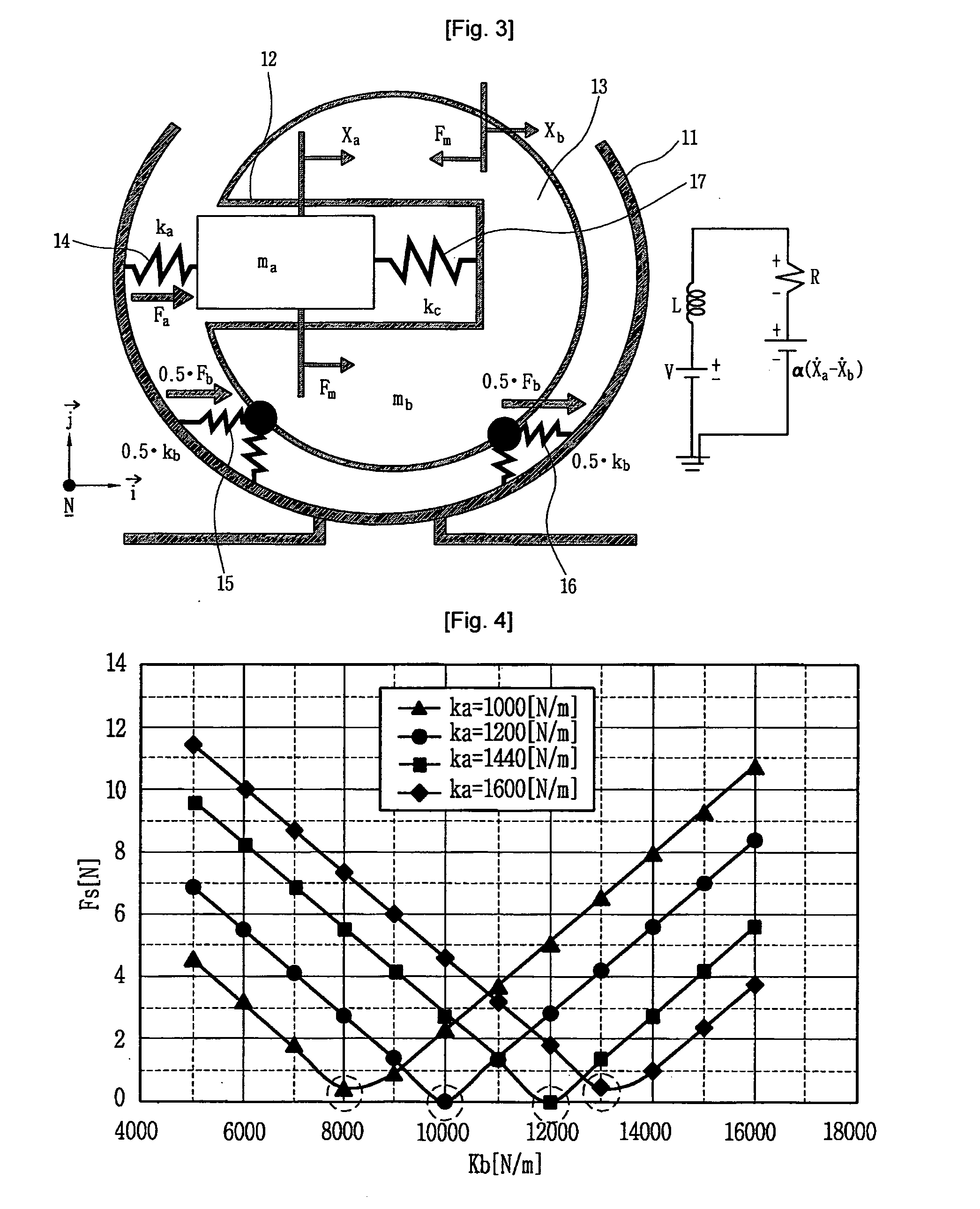
[0032]FIG. 3 is a schematic view illustrating a vibration system of a linear compressor according to an embodiment of the present invention.

[0033]The vibration system of the linear compressor includes a shell 11, a moving part 12, a stationary part 13, a first elastic body 14, second elastic bodies 15 and 16, and a third elastic body 17. Variables used to interpret the vibration system include a displacement xa of the moving part 12, a displacement xb of the stationary part 13, a mass Ma of the moving part 12, a mass Mb of the stationary part 13, an spring constant ka of the first elastic body 14, an spring constant 0.5·kb of each second elastic body 15 and 16, an spring constant kc of the third elastic body 17, motor parameters L, R, α and V, a motor output Fm, a force Fa applied to the moving part 12 by the first elastic body 14, a force...


PUM


Abstract

The present invention provides a linear compressor having an elastic body capable of reducing vibration transferred to a shell due to a motion of a moving part. The linear compressor includes a shell defining a hermetic space, a stationary part installed in the shell and having a mass of Mb, a moving part reciprocating linearly inside the stationary part at a frequency of ω to compress a fluid, and having a mass of Ma, a first elastic body having both ends supported on the moving part and the shell respectively, and having an spring constant of ka, a second elastic body having both ends supported on the shell and the stationary part respectively, and having an spring constant of kb, and a third elastic body having both ends supported on the stationary part and the moving part respectively, and having an spring constant of k. The frequency ω satisfies ω2>(ka / Ma). In the above configuration, the spring constant kc of the third elastic body is always a positive number, so that the third elastic body can be implemented with a mechanical elastic body more easily designed and controlled than a gas elastic body.

Description

TECHNICAL FIELD [0001]The present invention relates to a linear compressor, and more particularly, to a linear compressor having an elastic body to prevent a shell from being vibrated due to a motion of a moving part.BACKGROUND ART [0002]In general, a compressor is a mechanical apparatus that receives power from a power generation apparatus such as an electric motor or a turbine and compresses air, refrigerant or various operation gases to raise a pressure. The compressor has been widely used in an electric home appliance such as a refrigerator and an air conditioner, or in the whole industry.[0003]The compressor is roughly classified into a reciprocating compressor wherein a compression space to / from which an operation gas is sucked and discharged is defined between a piston and a cylinder, and the piston reciprocates linearly inside the cylinder to compress refrigerant, a rotary compressor wherein a compression space to / from which an operation gas is sucked and discharged is defin...

Claims


Application Information

Patent Timeline
IPC IPC(8): F04B7/00
CPCF04B35/045F04B39/0044F04B39/121F05B2210/12F05B2210/14F05B2260/96F16F3/04F16F15/04F16F2230/22Y10S417/902
Inventor KANG, YANG-JUN
Owner LG ELECTRONICS INC
Learn More