
Battery pack of excellent productability and structural stability

Active Publication Date: 2010-04-22
LG ENERGY SOLUTION LTD
View PDF13 Cites 26 Cited by
  • Summary
  • Abstract
  • Description
  • Claims
  • Application Information

AI Technical Summary

Benefits of technology

[0010]Specifically, it is an object of the present invention to provide a battery pack wherein a positive temperature coefficient (PTC) element mounted on the top of a battery cell is formed in a specific structure to greatly simplify the assembly process of the battery pack, to minimize the volume of a member mounted on the top of the battery cell, and, at the same time, to secure an excellent weldability.
[0034]The battery pack may further include another insulative cap (bottom cap) coupled to the bottom of the battery cell in addition to the insulative cap coupled to the top of the battery cell. Furthermore, the battery pack may further include a sheathing film attached to the outer surface of the battery case of the battery cell. Consequently, it is possible to protect the battery cell against external impacts and to maintain the electrical insulation. Preferably, the sheathing film is attached to the outer surface of the battery case of the battery cell such that the sheathing film surrounds the downward extending portion of the insulative cap.

Problems solved by technology

As a result, the lithium secondary battery may be heated or explode due to the overcharge of the battery, the overcurrent in the battery, or other physical external impacts applied to the battery.
That is, the safety of the lithium secondary battery is very low.
However, it is difficult to fix the nickel plates to a battery case, which is made of aluminum, by welding.
Consequently, a plurality of members are used, and therefore, a dead space increases, with the result that the assembly process of the battery is complicated, and the capacity of the battery is reduced.
However, this coupling method complicates the assembly process of a battery pack and reduces the strength of the battery.
When physical impacts are applied to the battery cell, the reduction of the coupling strength induces the occurrence of a short circuit in the battery cell, with the result that the battery may catch fire and explode, and therefore, the safety of the battery is lowered.
However, the above-described technologies do not suggest a battery pack structure that is capable of providing a desired effect.

Method used


Image

  • Battery pack of excellent productability and structural stability
  • Battery pack of excellent productability and structural stability
  • Battery pack of excellent productability and structural stability

Examples


Embodiment Construction

[0047]Now, preferred embodiments of the present invention will be described in detail with reference to the accompanying drawings. It should be noted, however, that the scope of the present invention is not limited by the illustrated embodiments.

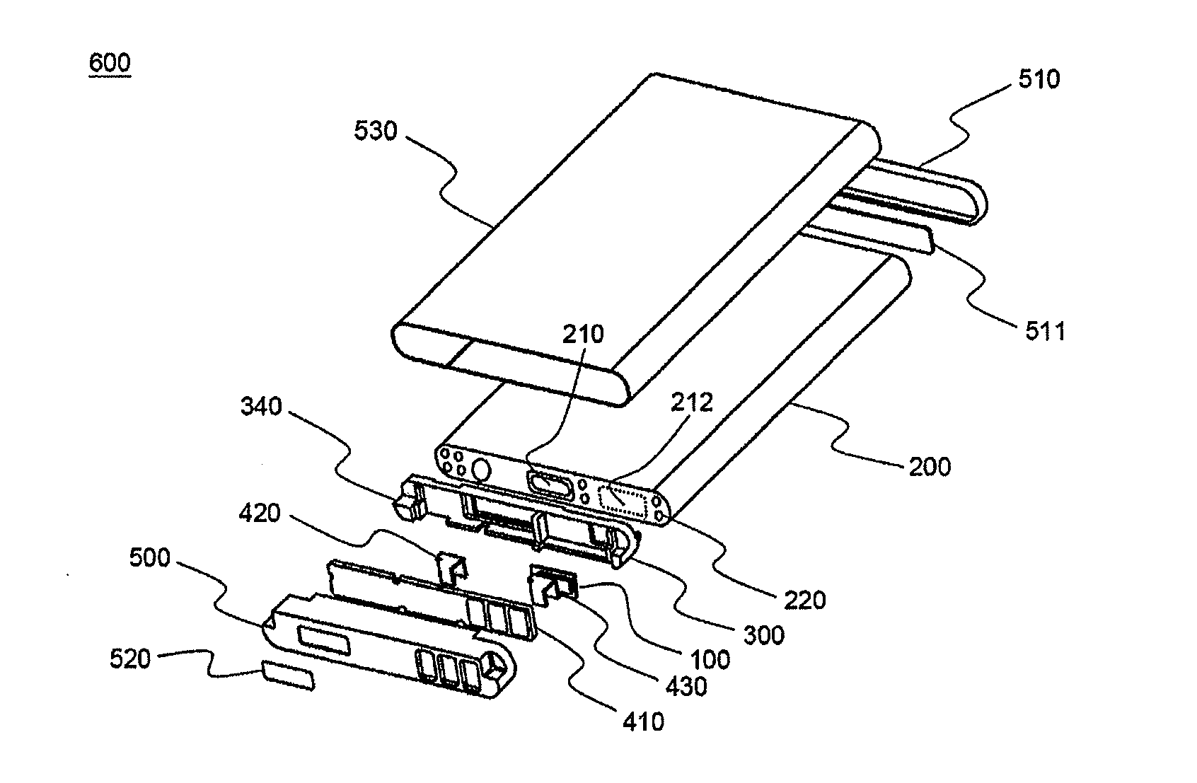
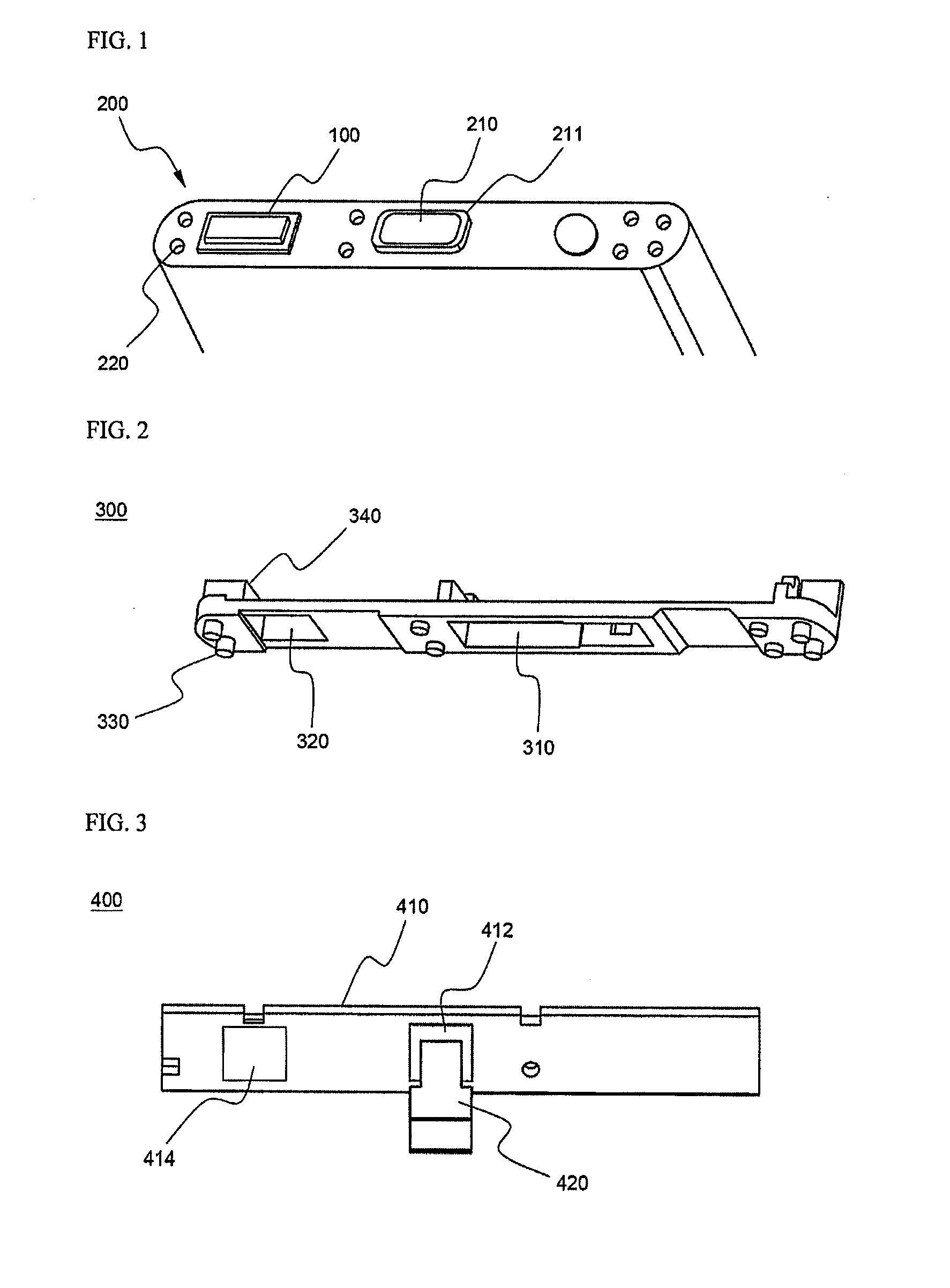
[0048]FIG. 1 is a partial perspective view illustrating the top of a battery cell according to a preferred embodiment of the present invention.

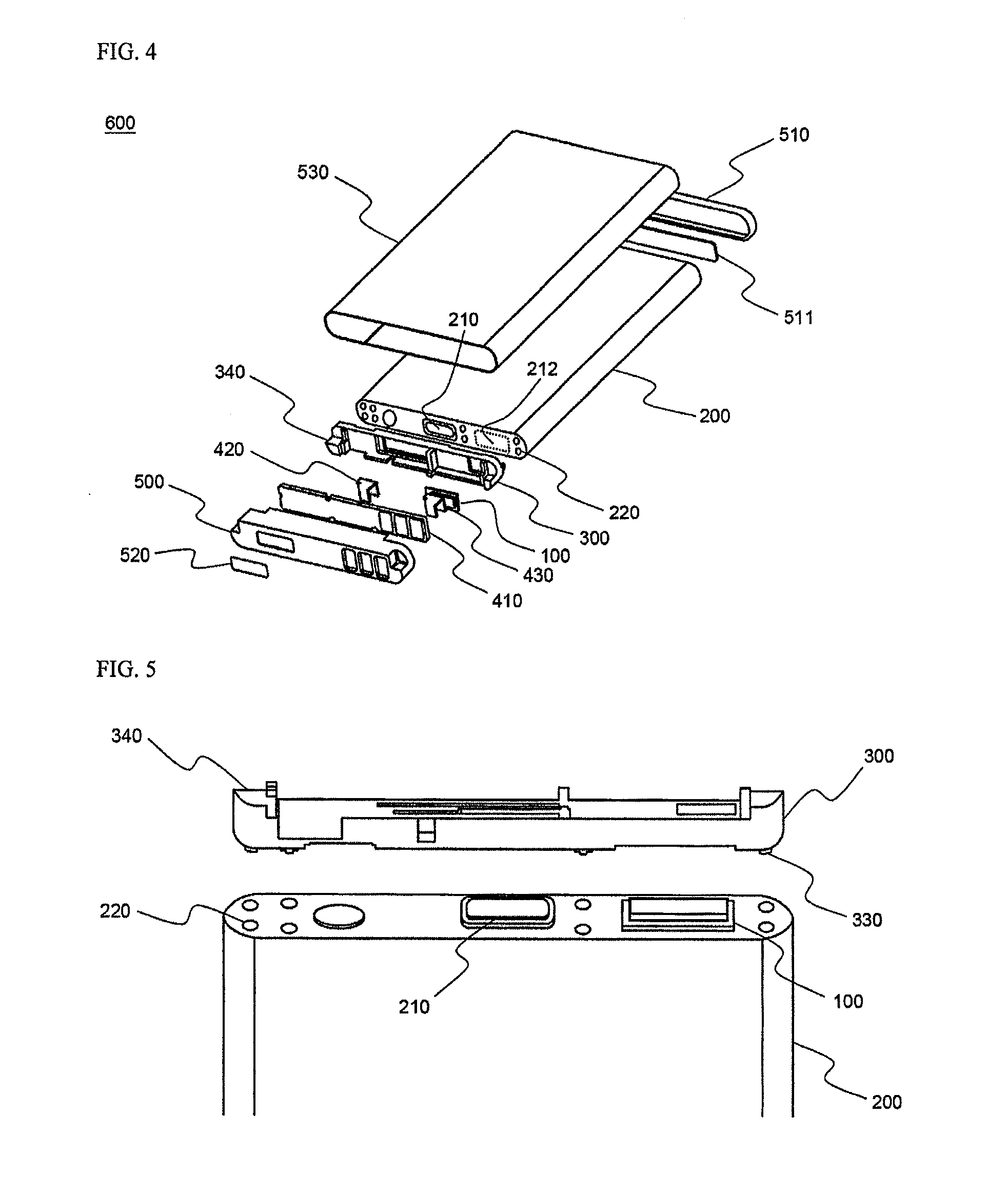
[0049]Referring to FIG. 1, the battery cell 200 is constructed in a structure in which an electrode assembly (not shown) of a cathode / separator / anode structure is mounted in a battery case (metal container) together with an electrolyte in a sealed state. An anode terminal 210 protrudes from the middle of the top of the battery cell 200. The metal container itself constitutes a cathode. The anode terminal 210 is electrically insulated from the metal container by an insulative member 221. At opposite sides of the top of the battery cell 200 are formed a plurality of coupling grooves 220, into which coup...


PUM


Abstract

Disclosed herein is a battery pack including a battery cell, an insulative mounting member coupled to the battery cell in a specific coupling structure, a positive temperature coefficient (PTC) element having a lower connection plate directly coupled to the battery cell while the lower connection plate is not bent, and an insulative cap, whereby the number of the members for electrical connection and electrical insulation is reduced, with the result that the assembly process of the battery pack is greatly simplified, the dead space is reduced, with the result that the capacity of the battery in the same-sized battery pack is maximized, and the structural stability of the battery pack against an external force is improved.

Description

FIELD OF THE INVENTION[0001]The present invention relates to a battery pack of excellent productability and structural stability, and, more particularly, to a battery pack including a battery cell, an insulative mounting member coupled to the battery cell in a specific coupling structure, a positive temperature coefficient (PTC) element having a lower connection plate directly coupled to the battery cell while the lower connection plate is not bent, and an insulative cap, whereby the number of the members for electrical connection and electrical insulation is reduced, with the result that the assembly process of the battery pack is greatly simplified, the dead space is reduced, with the result that the capacity of the battery in the same-sized battery pack is maximized, and the structural stability of the battery pack against an external force is improved.BACKGROUND OF THE INVENTION[0002]As mobile devices have been increasingly developed, and the demand of such mobile devices has in...

Claims


Application Information

Patent Timeline
IPC IPC(8): H01M14/00H01M50/119H01M50/147H01M50/50H01M50/55H01M50/572
CPCH01M2/0215H01M2/0217H01M2/0267H01M2/0275H01M2200/106H01M2/0404H01M2/20H01M2/34H01M10/425H01M2/0285Y02E60/10H01M50/103H01M50/147H01M50/50H01M50/572H01M50/55H01M50/119H01M50/555H01M50/209
Inventor LEE, CHEOL WOONGMOON, KI EOB
Owner LG ENERGY SOLUTION LTD
Learn More