
Method for changing route in wireless communication

a wireless communication and route technology, applied in the field of route technology in wireless communication, can solve the problems of poor route change accuracy, inability to carry out a timely route change for an ss/ms, and to be switched to an unsuitable route, so as to achieve effective avoid failure, reduce delay in route change, and improve accuracy

Inactive Publication Date: 2010-04-22
NOKIA SOLUTIONS & NETWORKS OY
View PDF2 Cites 107 Cited by
  • Summary
  • Abstract
  • Description
  • Claims
  • Application Information

AI Technical Summary

Benefits of technology

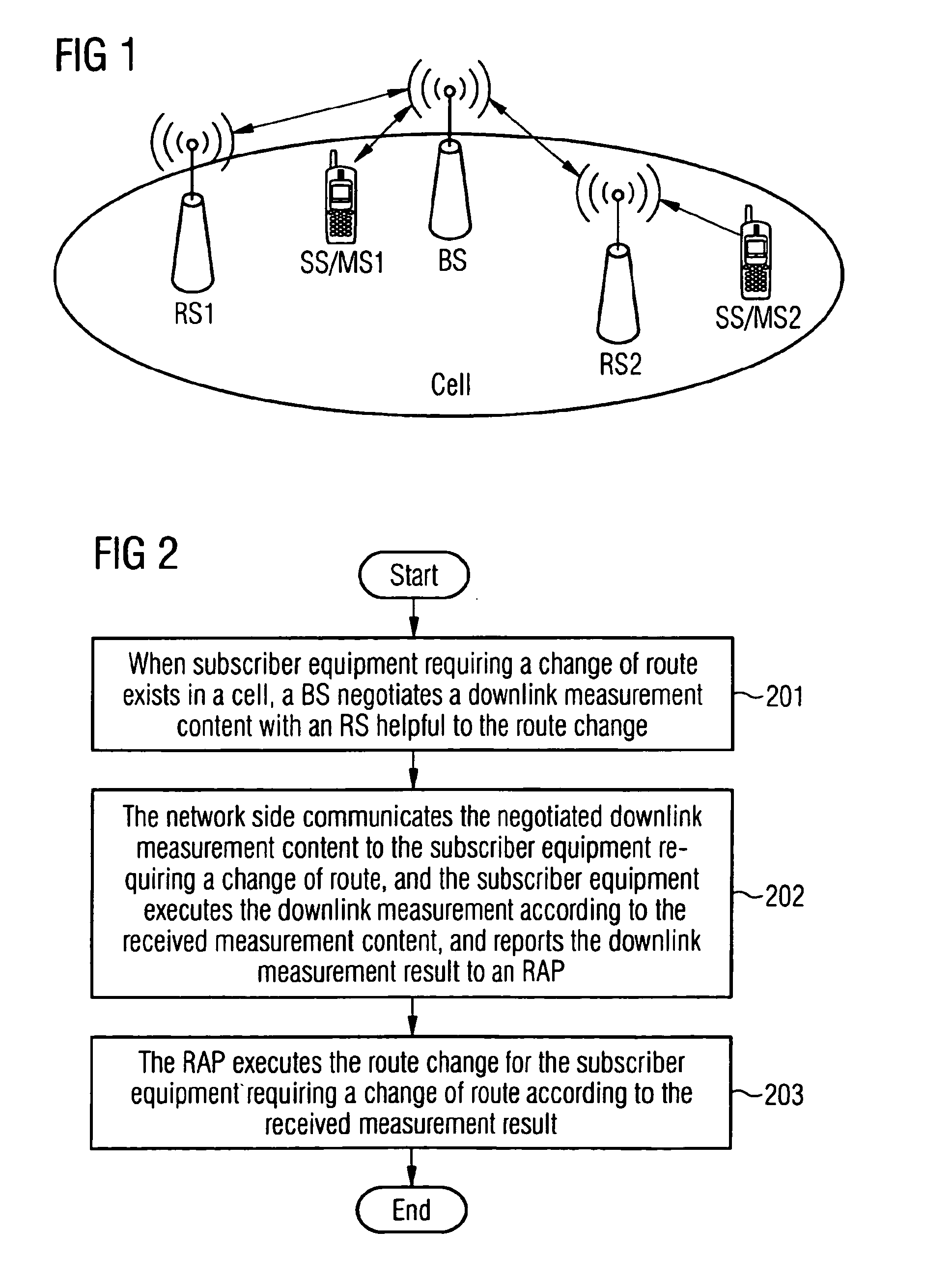
[0008]A. when there is subscriber equipment requesting a change of route in a cell, a BS negotiates downlink measurement contents with a relay station facilitating the route change in the cell;
[0059]Finally, a route change request message and a route change response message needed during a route change can be mapped to the commands specified in the IEEE 802.16 protocol, namely the existing commands of the protocol can be utilized in realizing the route change. Therefore, during execution of the method, only a few changes to the original network operation are needed, and the operability is better.

Problems solved by technology

However, in practical applications, when the uplink conditions differ from those of the downlink and the uplink and the downlink are separate, the uplink measurement results cannot reflect the downlink conditions, and then the BS will use the inaccurate measurement results as a basis for changing the route, which will cause the SS / MS to be switched to an unsuitable route and lead to poor accuracy in route changing.
In addition, since the timing of the action in which an SS / MS transmits information to a BS or RS through an uplink may be interrupted, when there is no information sent from SS / MS over the uplink, a BS or RS cannot execute the uplink measurement, thereby making it impossible to carry out a timely route change for an SS / MS.

Method used


Image

  • Method for changing route in wireless communication
  • Method for changing route in wireless communication
  • Method for changing route in wireless communication

Examples


embodiment 1

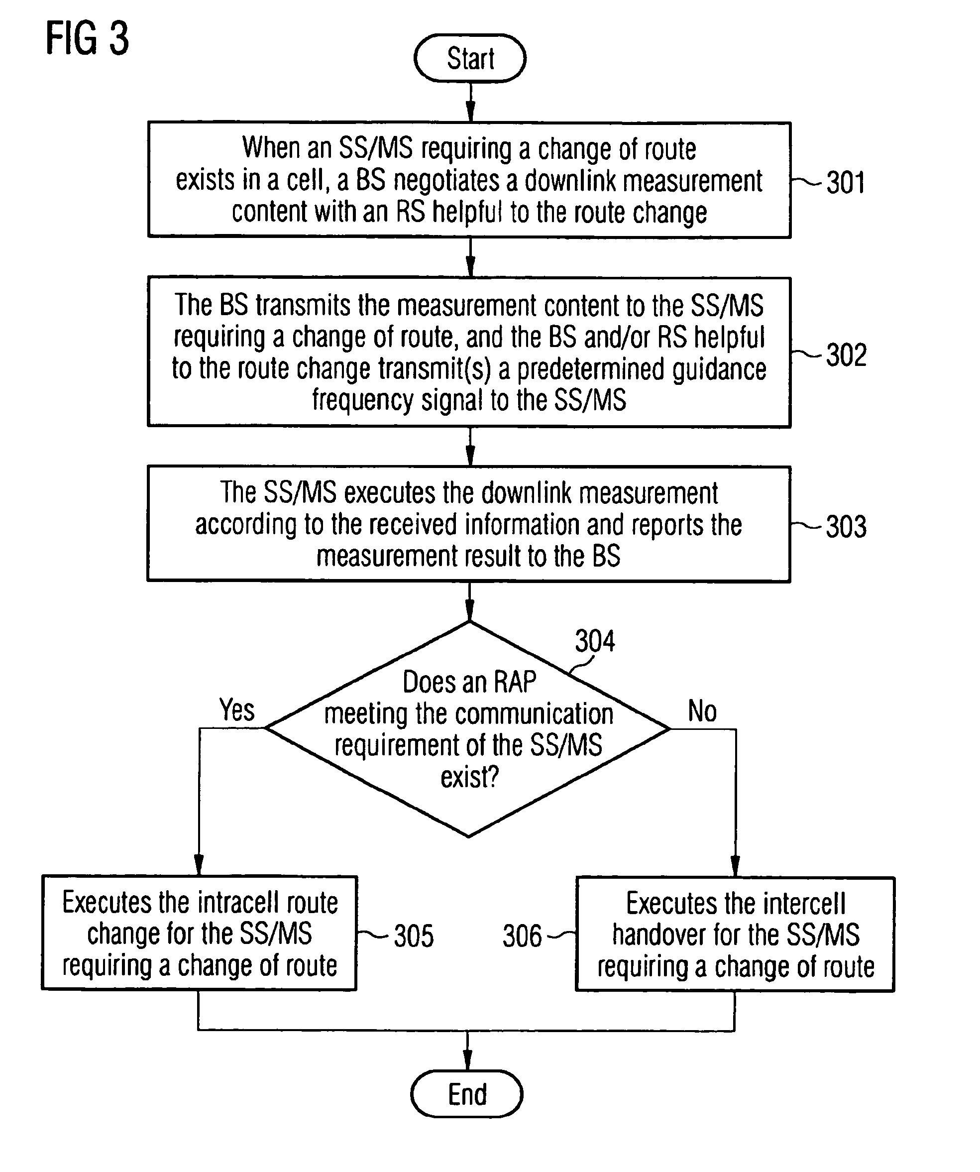
[0072]In this embodiment, a long-term and fixed wireless resources division scheme is adopted, that is to say that, within a time of superframe level, such as 10 seconds or 1 minute, orthogonal wireless resources are assigned to each RAP in the cell. For example, if the wireless resources are 2M (bandwidth)×2 ms, a first half of the wireless resources therein, namely 1M (bandwidth)×2 ms, is assigned to the BS and the second half of the wireless resources, namely 1M (bandwidth)×2 ms, are assigned to the RS in the cell, and the resources occupied by each RAP are fixed within this time slot. In addition, in order to facilitate the subscriber equipment's execution of the downlink measurement, after the BS has negotiated with the RS facilitating the route change in this embodiment it transmits a predetermined pilot signal to the subscriber equipment via the downlink.

[0073]FIG. 3 shows a flowchart of the method for changing a route in this embodiment. Referring to FIG. 3, the method of th...

embodiment 2

[0090]In this embodiment, a dynamic wireless resources allocation scheme is adopted in the cell. In this case, the resources assigned to each RAP in the cell are not fixed for a period of time, but vary dynamically. However, it is similar to embodiment 1 in that, in order to facilitate the subscriber equipment's execution of the downlink measurement, in this embodiment after having negotiated with the RS, the BS also transmits the predetermined guidance signal to the subscriber equipment via the downlink.

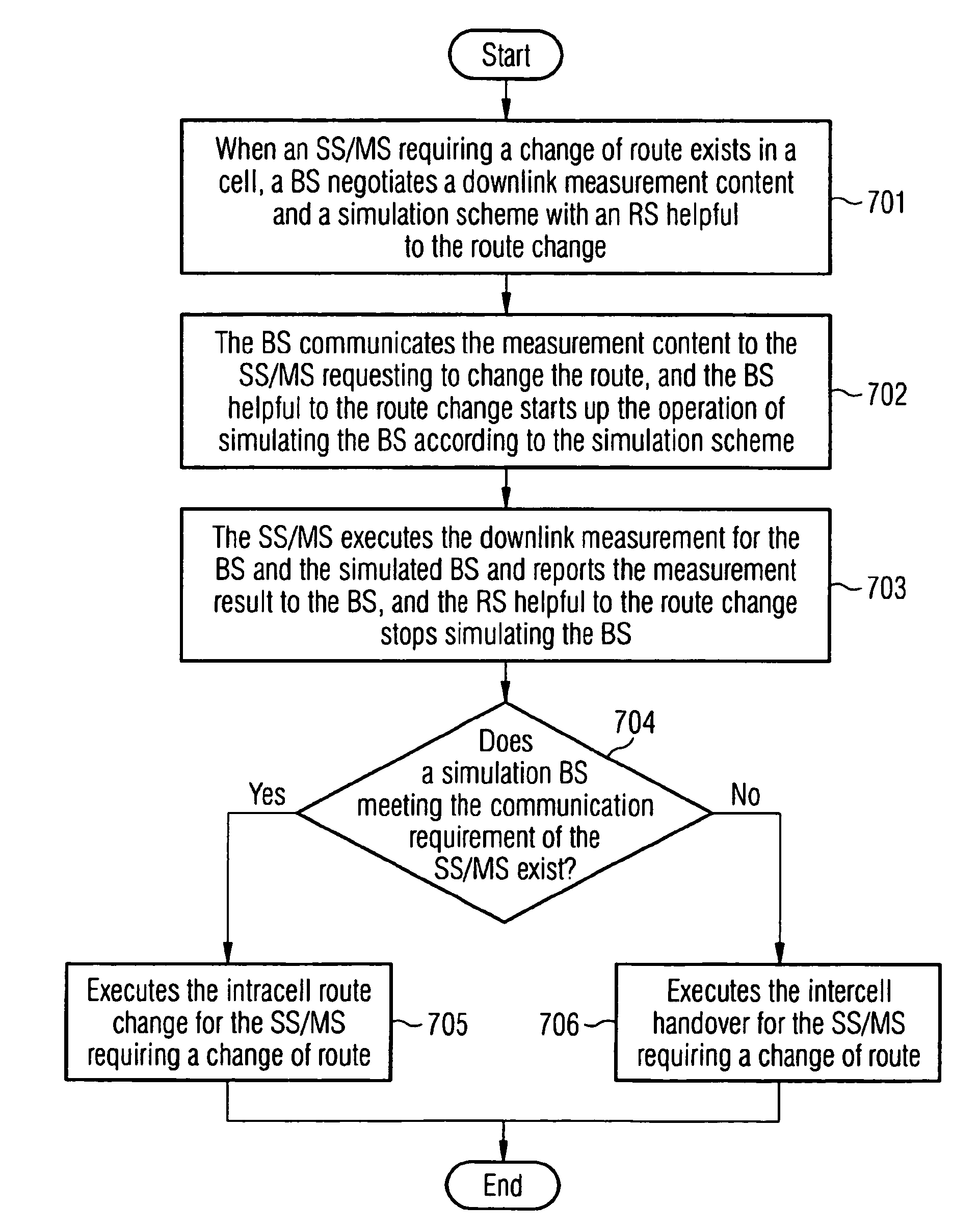
[0091]FIG. 4 shows a flowchart of the method for changing a route in this embodiment. Referring to FIG. 4, the method of this embodiment comprises:[0092]in step 401, when the cell contains an SS / MS requesting the route change, a BS negotiates the downlink measurement contents and a resource allocation scheme with an RS facilitating the route change.

[0093]Since a dynamic wireless resources allocation scheme is adopted in this embodiment, at the same time when negotiating the downlink...

embodiment 3

[0102]In this embodiment, the long-term and fixed wireless resources allocation scheme is adopted in a cell, that is to say, within a superframe level, such as 10 seconds or 1 minute, fixed orthogonal wireless resources are assigned to each RAP in the cell, and the resources taken up by each RS are fixed in this long period of time. In addition, in contrast to the embodiments 1 and 2; no guidance signal is predetermined in this embodiment, but before the SS / MS requiring the route change executes the downlink measurement a data sequence is transmitted by the BS and the RS facilitating the route change over the downlink.

[0103]FIG. 5 shows a flowchart of the method for changing a route in this embodiment; referring to FIG. 5, the method of this embodiment comprises:[0104]in step 501, when the cell contains an SS / MS requesting a change of route, a BS negotiates the downlink measurement contents with an RS facilitating the route change.

[0105]The operation in this step is the same as that...


PUM


Abstract

A method for changing a route in wireless communication involves: when there is subscriber equipment requesting a change of route in a cell, a base station negotiates downlink measurement contents with a relay station facilitating the route change in the cell; a network side informs the subscriber equipment requesting a change of route of the negotiated downlink measurement contents, and the subscriber equipment executes a downlink measurement according to the received measurement contents and reports the downlink measurement results to a radio access point; and the radio access point executes the route change for said subscriber equipment according to the received measurement results. The method can effectively improve the accuracy of the route change and alleviate the delay due to the route change.

Description

CROSS REFERENCE TO RELATED APPLICATIONS[0001]This application is based on and hereby claims priority to PCT Application No. PCT / EP2008 / 051140 filed on Jan. 30, 2008 and CN Application No. 200710063173.8 filed on Jan. 30, 2007, the contents of which are hereby incorporated by reference.BACKGROUND OF THE INVENTION[0002]The present invention relates to a route technology in wireless communication, and particularly to a method for changing a route in wireless communication.[0003]With the continuous developments in wireless communication technology and the increasing requirements by wireless communication users, cellular communication systems may change from the conventional single-hop form to a multi-hop form. For example, the Institute for Electrical and Electronic Engineers (IEEE) recently proposed the introduction of relay stations (RS) into the cellular systems on account of IEEE 802.16, so as to construct a multi-hop cell structure with a cell coverage jointly provided by a base st...

Claims


Application Information

Patent Timeline
Patent Type & Authority Applications(United States)
IPC IPC(8): H04W40/02H04W36/12H04W16/26H04W36/30H04W40/22H04W40/36H04W84/04
CPCH04B7/2606H04W16/26H04W84/047H04W40/22H04W40/36H04W36/30H04W36/302
Inventor LI, HUILI, PINGWANG, LANXUE, YI SHENGZIRWAS, WOLFGANG
Owner NOKIA SOLUTIONS & NETWORKS OY
Learn More