Hemostatic implant

a technology of implants and hematopoietic stem cells, applied in the field of implants, can solve the problems of complex formulation of solutions, significant limitations of in situ hemostatic therapy,

Inactive Publication Date: 2010-04-22
TYCO HEALTHCARE GRP LP
View PDF17 Cites 583 Cited by
  • Summary
  • Abstract
  • Description
  • Claims
  • Application Information

AI Technical Summary

Benefits of technology

[0007]The present implants include a porous substrate having a first hydrogel precursor applied to a first portion of the porous substrate and a second hydrogel precursor applied to a second portion of the porous substrate. In embodiments, at least one of the first or second hydrogel precursors is applied to the porous substrate as a film. In embodiments, the first portion of the substrate having the first hydrogel precursor applied thereto is spatially separated from the second portion of the porous substrate to prevent the first and second hydrogel precursors from reacting with each other until the implant is placed at the site of implantation and exposed to the physiological fluids of a patient. Exposure of the implant to physiological fluids causes the first hydrogel precursor to migrate from the first portion of the porous substrate towards the second portion of the porous substrate and react with the second hydrogel precursor. In embodiments, the present implants display not only hemostatic properties but further display anti-adhesive properties on portions of the coated porous substrate.

Problems solved by technology

However, significant limitations exist when using solutions for in situ hemostatic therapy.
Furthermore, formulation of the solutions may be complex, as preparation of precursor solutions typically requires reconstitution of the precursors, or, when the solutions are stored frozen, thawing.

Method used


Image

  • Hemostatic implant
  • Hemostatic implant
  • Hemostatic implant

Examples


example

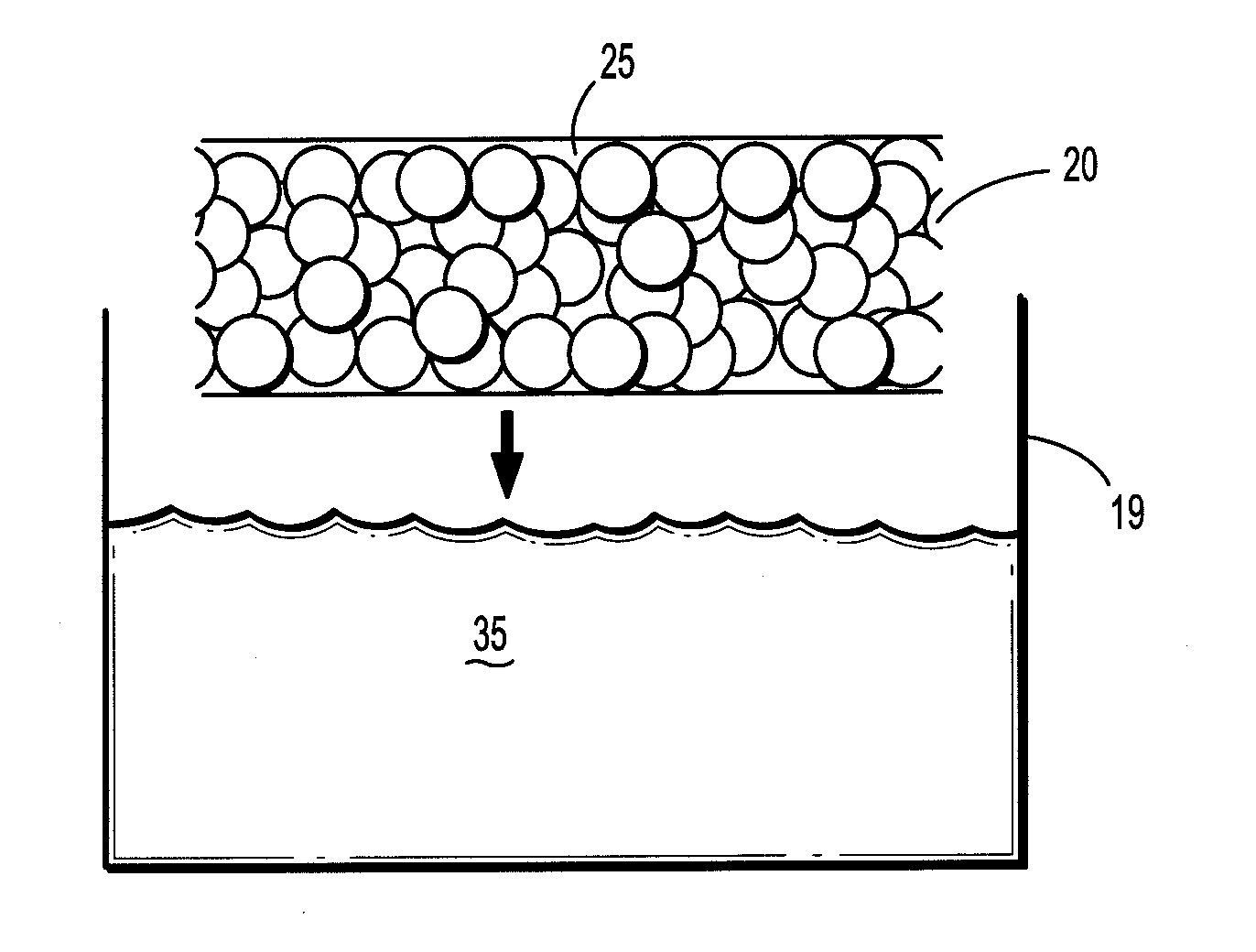
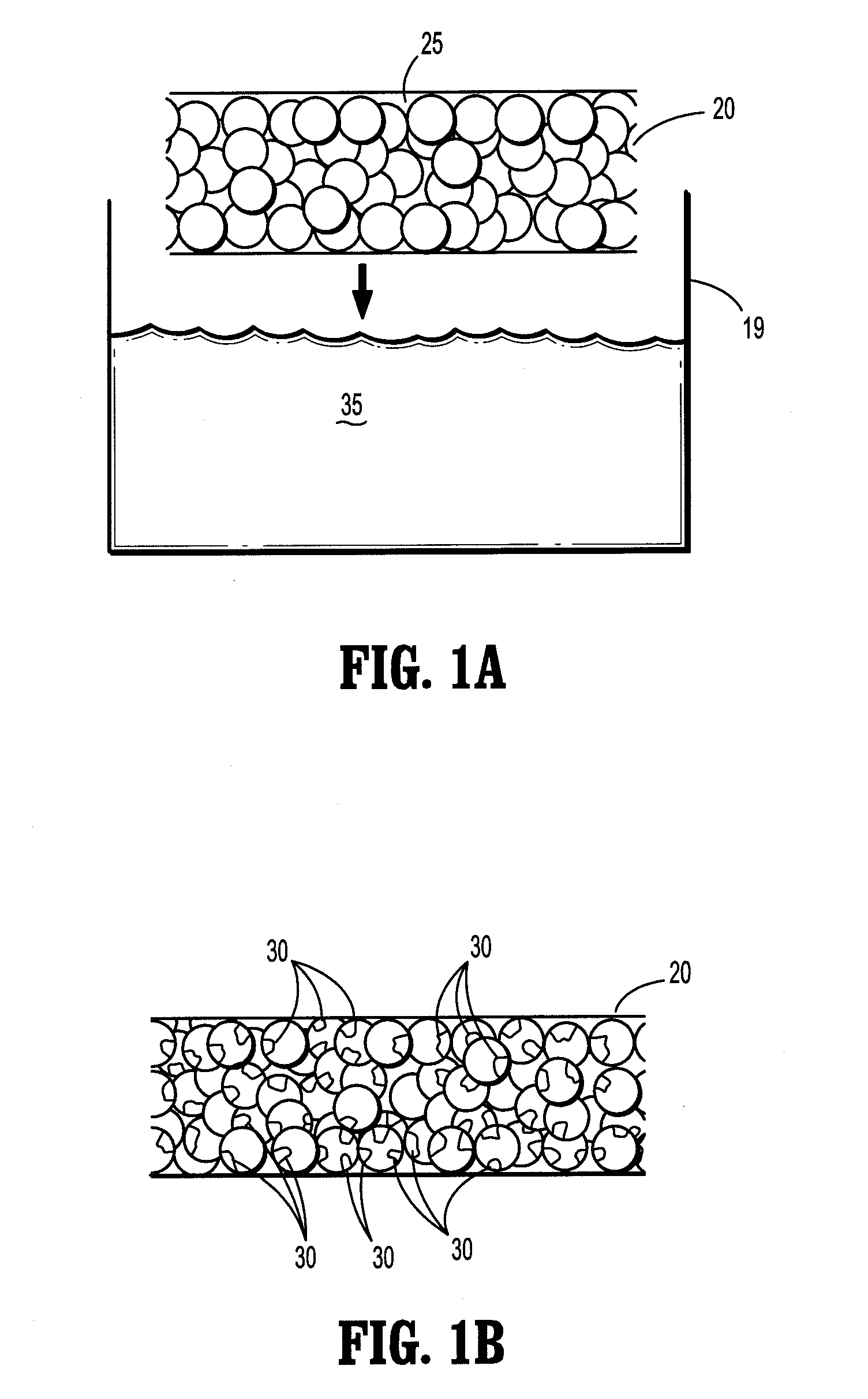
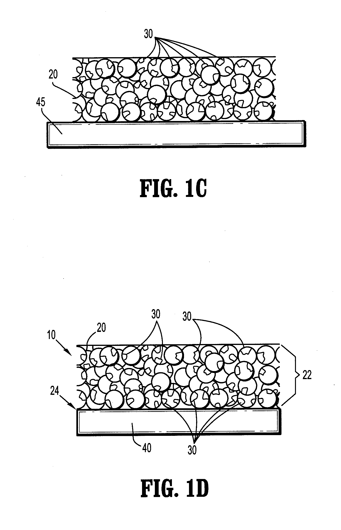
[0070]A saturated borate buffer solution of trilysine is prepared. The solution contains 20.6 milligrams of trilysine per milliliter of solution. The pH of the solution is about 9.2. A sheet of oxidized cellulose is dipped into the solution and then fixed to a rack for drying. The rack is placed into a vacuum oven. The oven is pumped down to about 50 mTorr and kept at a temperature of about 25° C. for about three days to reduce the moisture level to less than 2% by weight. An eight aim N-hydroxysuccinimidyl-functionalized polyethylene glycol having a molecular weight of about fifteen thousand is melted at about 50° C. on a hot plate. The dried trilysine-containing oxidized cellulose sheet is placed into contact with the melted PEG component. After cooling, the PEG component forms a film on one side of the implant.

[0071]The resulting product is trimmed to a 2 inch by 2 inch square, dried and packaged in a foil container.

[0072]In use, the foil package is opened and the implant is appl...


PUM

PropertyMeasurementUnit
sizeaaaaaaaaaa
sizeaaaaaaaaaa
molecular weightaaaaaaaaaa

Abstract

The present disclosure relates to hemostatic implants including a porous substrate having a first hydrogel precursor and a second hydrogel precursor applied thereto in a manner such that the first hydrogel precursor and second hydrogel precursor do not react with each other until the implant is placed at the site of implantation and exposed to the physiological fluids of a patient.

Description

RELATED APPLICATIONS[0001]This application claims priority to U.S. Provisional Application No. 61 / 196,543 filed Oct. 17, 2009.BACKGROUND[0002]1. Technical Field[0003]The present disclosure relates to implants and more particularly to hemostatic implants which include a porous substrate having a first hydrogel precursor and a second hydrogel precursor applied thereto.[0004]2. Background of Related Art[0005]In situ hemostatic therapy has primarily focused on the transformation of precursor solutions into solids within a patient's body. Transformations have been achieved by a variety of means, including precipitation, polymerization, crosslinking, and desolvation. However, significant limitations exist when using solutions for in situ hemostatic therapy. Solutions of low viscosity may flow away and be cleared from an application site before transformation and solidification occurs. Furthermore, formulation of the solutions may be complex, as preparation of precursor solutions typically...

Claims


Application Information

Patent Timeline
Patent Type & Authority Applications(United States)
IPC IPC(8): A61B17/03
CPCA61L31/042A61L31/10A61L31/129A61L31/145A61L2400/04A61L31/146C08L1/04
Inventor BENNETT, STEVEN
Owner TYCO HEALTHCARE GRP LP
Why Eureka
Try Eureka