Vehicle and driving system for vehicle installation

a technology for installing vehicles and driving systems, which is applied in the direction of driver input parameters, external condition input parameters, electric devices, etc., can solve the problems of slow increase of inability to ensure a quick response of the motor, and disappointingly slow torque output of the driver. , to achieve the effect of reducing the output torque of the motor, increasing the output torque, and reducing the driving distan

Active Publication Date: 2010-04-22
TOYOTA JIDOSHA KK +2
View PDF3 Cites 20 Cited by
  • Summary
  • Abstract
  • Description
  • Claims
  • Application Information

AI Technical Summary

Benefits of technology

[0010]In one preferable application of the first vehicle according to the above aspect of the invention, the decrease rate setting module sets the decrease rate to have an increasing tendency with an increase of the detected accelerator operation amount. The preset back motion of the vehicle is thus achieved more quickly against the greater accelerator operation amount or the driver's greater driving demand. This enables the vehicle to be released immediately from the vehicle stop state with output of the corresponding torque based on the driver's accelerator operation amount from the motor. In this application, the decrease rate is set to have a decreasing tendency with a decrease of the detected accelerator operation amount. This moves the vehicle back slowly and improves the ride quality.
[0028]On condition that there is no substantial change of the detected accelerator operation amount and that the predetermined torque decrease increase condition is satisfied in the substantial vehicle stop state, the second control method according to the above aspect of the invention controls the motor to decrease the output torque of the motor by the first change rate until the preset back motion of the vehicle and to increase the output torque of the motor by the second change rate based on the detected accelerator operation amount and the detected gradient-reflecting physical quantity after the preset back motion of the vehicle. The smaller amount of accelerator operation generally suggests the driver's smaller driving demand. On condition that the vehicle stops on the road surface of a gentle slope, the small amount of accelerator operation may reflect not the driver's vehicle stop request but the driver's driving demand. On condition that the vehicle stops on the road surface of a steep slope, on the other hand, the large amount of accelerator operation may reflect not the driver's driving demand but the driver's vehicle stop request. Increasing the output torque of the motor by the second change rate based on the detected accelerator operation amount and the detected gradient-reflecting physical quantity after the preset back motion of the vehicle assures the control by taking into account the driver's driving demand. The terminology of ‘preset back motion’ includes a back motion to a certain extent that causes a changeover of a current crowding phase among respective coil phases of the motor.

Problems solved by technology

Continuation of the accelerated heat generation in the second motor and in the driving circuit may cause a heat-induced damage in the second motor or in the driving circuit.
In the torque increase control, a slow increase of the output torque of the motor does not ensure a quick response of the motor for outputting a torque based on the driver's driving demand to the driver's subsequent depression of the accelerator pedal.
The driver accordingly feels disappointingly slow torque output.

Method used


Image

  • Vehicle and driving system for vehicle installation
  • Vehicle and driving system for vehicle installation
  • Vehicle and driving system for vehicle installation

Examples


first embodiment

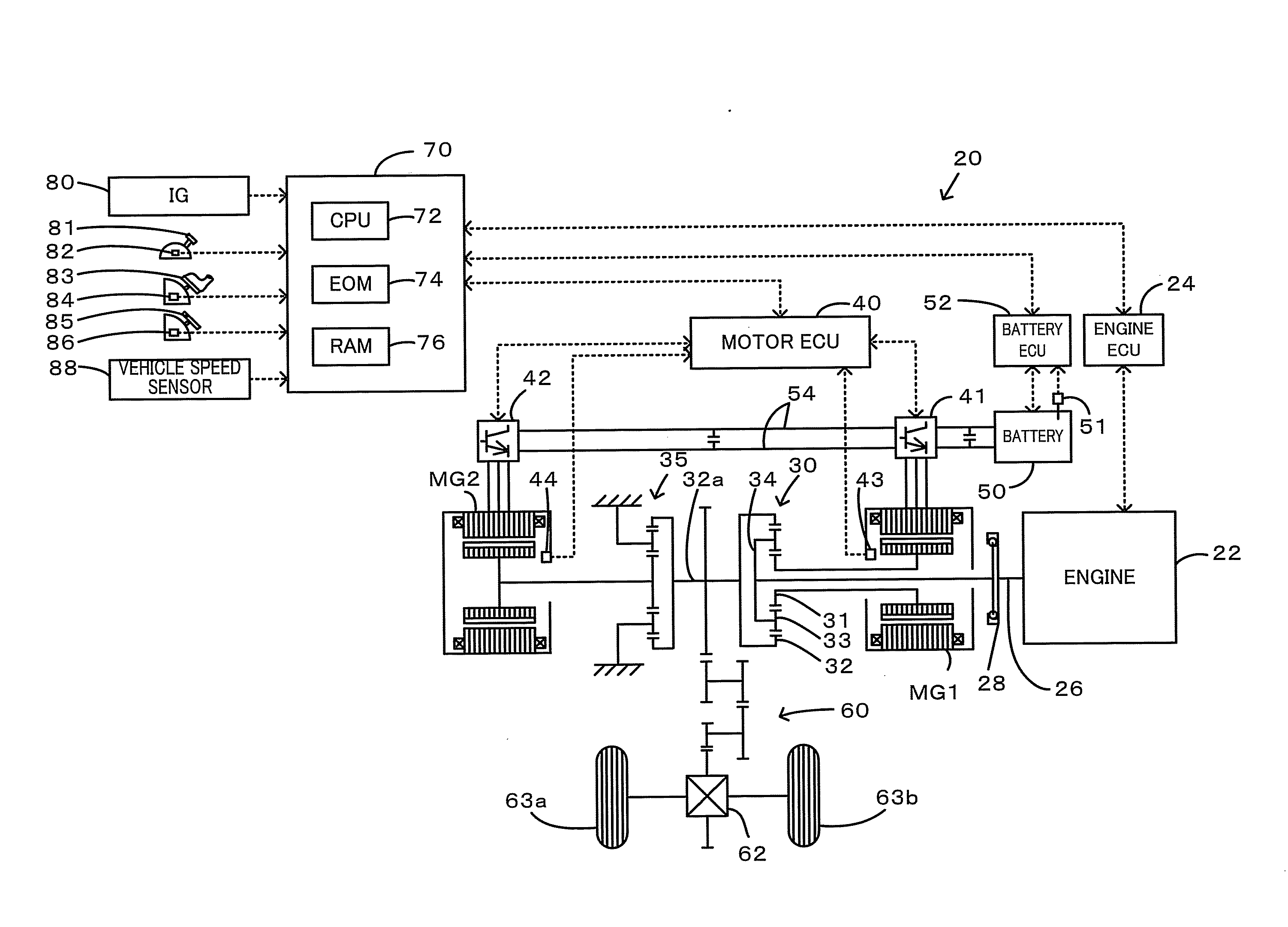
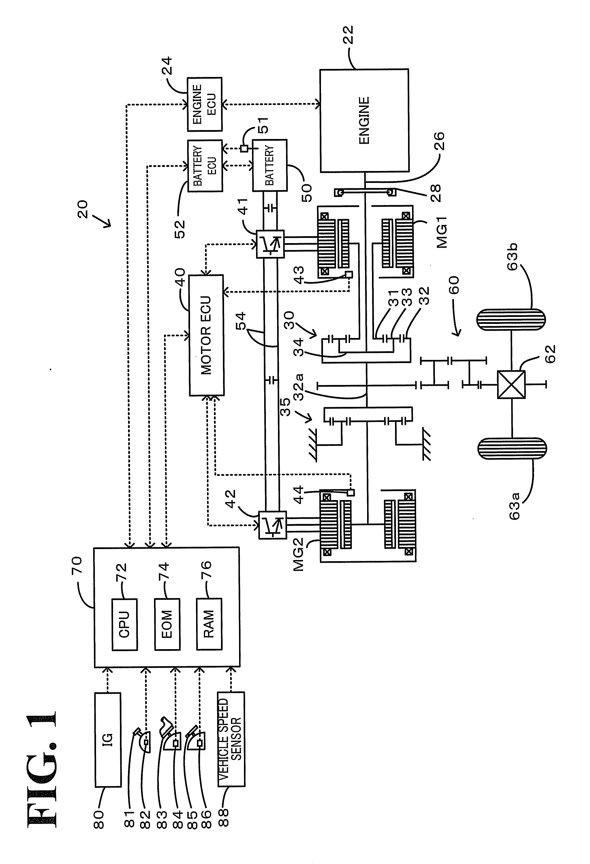
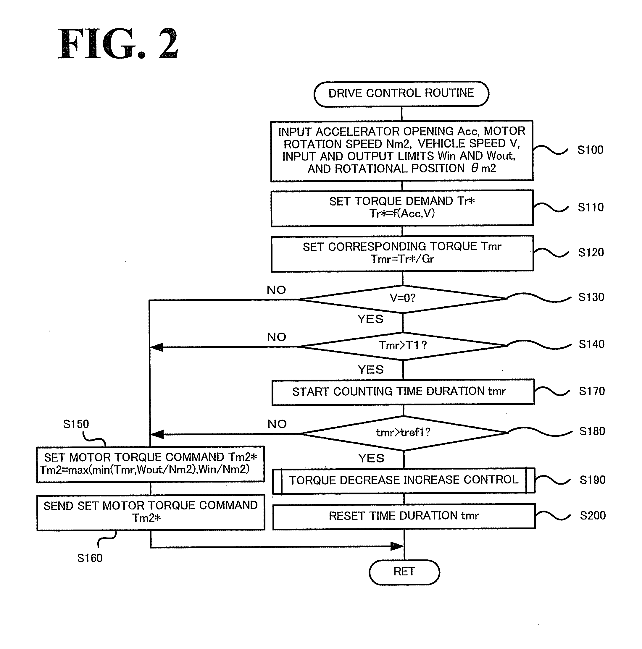
[0054]The following describes the operations of the hybrid vehicle 20 of the first embodiment having the configuration discussed above, especially series of processing at a vehicle stop with output of a torque from the motor MG2 corresponding to the driver's accelerator operation. FIG. 2 is a flowchart showing a drive control routine executed by the hybrid electronic control unit 70. This routine is repeatedly performed at preset time intervals (for example, at every several msec) except the processing of steps S190 and S200. It is here assumed that the hybrid vehicle 20 is under operation control in the motor drive mode to ensure output of a power equivalent to a power demand from the motor MG2 to the ring gear shaft 32a at an operation stop of the engine 22 on an upslope.

[0055]In the drive control routine, the CPU 72 of the hybrid electronic control unit 70 first inputs various data required for control, for example, the accelerator opening Acc from the accelerator pedal position ...

second embodiment

[0086]The following describes the operations of the electric vehicle 320 of the second embodiment having the configuration discussed above. FIG. 11 is a flowchart showing a drive control routine executed by the electronic control unit 340.

[0087]In the drive control routine, the CPU 342 of the electronic control unit 340 first inputs various data required for control, for example, the accelerator opening Acc from the accelerator pedal position sensor 354, the vehicle speed V from the vehicle speed sensor 358, and the motor rotational position θm from the rotational position detection sensor 323 (step S500). The CPU 342 subsequently sets a torque demand Td* to be output to the driveshaft 332, based on the input accelerator opening Acc and the input vehicle speed V (step S510). A concrete procedure of setting the torque demand Td* in the second embodiment provides and stores in advance variations in torque demand Td* against the vehicle speed V with regard to various settings of the ac...


PUM


Abstract

On condition that output of a torque of not lower than a preset reference torque from a motor continues for at least a predetermined time period in a vehicle stop state with output of a corresponding torque from the a second motor based on a detected accelerator opening, a torque command of the second motor is set to decrease the output torque of said motor by a torque decrease rate, which is set according to the corresponding torque and the accelerator opening in the vehicle stop state (initial accelerator opening). After a changeover of a current crowding phase in the second motor, the torque command of said motor is set to increase the output torque of said motor by a torque increase rate, which is set according to the accelerator opening in the vehicle stop state.

Description

TECHNICAL FIELD[0001]The present invention relates to a vehicle and a driving system for vehicle installation.BACKGROUND ART[0002]One proposed structure of the vehicle includes an engine, a planetary gear mechanism having a carrier connected to a crankshaft of the engine and a ring gear linked with an axle, a first motor having a rotating shaft connected with a sun gear of the planetary gear mechanism, and a second motor having a rotating shaft connected with the ring gear of the planetary gear mechanism (see, for example, Patent Document 1).Patent Document 1: Japanese Patent Laid-Open No. H11-215687[0003]Another proposed structure of the vehicle is driven with output power of a motor (see, for example, Patent Document 2). In a vehicle stop state on an upslope with the accelerator opening kept at a substantially constant level, that is, in a current crowding state of the vehicle with concentric flow of electric current only in one specific phase among the respective coil phases of t...

Claims


Application Information

Patent Timeline
Patent Type & Authority Applications(United States)
IPC IPC(8): G06F19/00B60W30/18
CPCB60K1/02Y02T10/7275B60K6/445B60K6/448B60K6/547B60L15/20B60L2210/20B60L2240/421B60L2240/423B60L2240/486B60L2240/642B60L2240/80B60L2260/22B60W10/08B60W20/00B60W30/18036B60W30/18054B60W2510/081B60W2520/10B60W2540/10B60W2540/12B60W2540/16B60W2550/142B60W2710/083B60W2710/085F16H2037/0866Y02T10/6239Y02T10/6243Y02T10/642Y02T10/725Y02T10/7291Y02T90/16B60K6/365B60W2552/15Y02T10/62Y02T10/64Y02T10/72B60L3/06B60W30/1843B60W2510/087B60W2510/083
Inventor AOKI, TAKESHIOKASAKA, KAZUOMITAJIMA, YOICHIUEOKA, KIYOSHIRO
Owner TOYOTA JIDOSHA KK
Why Eureka
Try Eureka