Engineered, Scalable Underground Storage System and Method

a storage system and scalable technology, applied in the direction of transportation and packaging, sealing/packing, well accessories, etc., can solve the problems of not being able to scale to meet the performance needs and other requirements of a particular application, and cannot be used in the place of storage, so as to enhance the reliability of the (caes) system, maximize the capacity of the reservoir, and enhance the porosity and permeability of the formation

Inactive Publication Date: 2010-04-29
SEQENERGY
View PDF12 Cites 21 Cited by
  • Summary
  • Abstract
  • Description
  • Claims
  • Application Information

AI Technical Summary

Benefits of technology

[0012]Another object of the invention is to provide multiple independent reservoirs suitably isolatable for redundancy and enhanced reliability of the (CAES) system.
[0013]These and other objects are achieved in accordance with the invention by providing an engineered, scalable underground containment system and method for storing compressed gases or liquids in permeable rock formations using conventional drilling techniques. The porosity and permeability of the formation may be enhanced to maximize reservoir capacity and increase the rate at which gases and liquids can be introduced into and removed from the reservoir. In some embodiments, layers of cap rock in the formation are utilized as containment barriers, and in some containment barriers are constructed around the storage zones.

Problems solved by technology

A major disadvantage is that reservoirs of this nature can only be used where they are found.
They cannot be positioned where storage is needed, and they cannot be scaled to meet the performance needs and other requirements of a particular application.
Major disadvantages of the present natural gas storage models include: 1) depleted reservoirs generally are not designed to enable rapid injection and withdrawal of gas, 2) there is a limited number of salt domes or saline aquifers and these are not located heterogeneously throughout the country, 3) access to these sources is limited to their license holders, and 4) leakage has been a problem in the natural gas storage industry.
While (CAES) has been a proven technology and applied for over twenty years, to date, for a variety of reasons, (CAES) has been somewhat limited in its application.
If (CAES) is to meet the needs of the alternative energy industry, a major limiting factor is likely to be the difficulty in locating acceptable reservoirs.
The U.S. Department of Energy is investing significant amounts of money in assessing the efficacy of sequestering CO2 in active or depleted oil and gas fields, but the extent to which CO2 can be sequestered in such fields is probably limited by the fact that oil and gas fields often leak even when they are plugged and abandoned.
Four significant disadvantages exist in the present CO2 sequestration models being investigated: 1) EOR does not secure CO2 storage reliably, 2) natural reservoirs are difficult to discover, qualify and to get clear ownership of, 3) most natural reservoirs and oil and gas fields leak, 4) saline water in natural reservoirs can interact with the substance being stored, and 5) natural reservoirs and oil and gas fields can be a very long distance from the sources of the captured CO2.

Method used


Image

  • Engineered, Scalable Underground Storage System and Method
  • Engineered, Scalable Underground Storage System and Method
  • Engineered, Scalable Underground Storage System and Method

Examples


Embodiment Construction

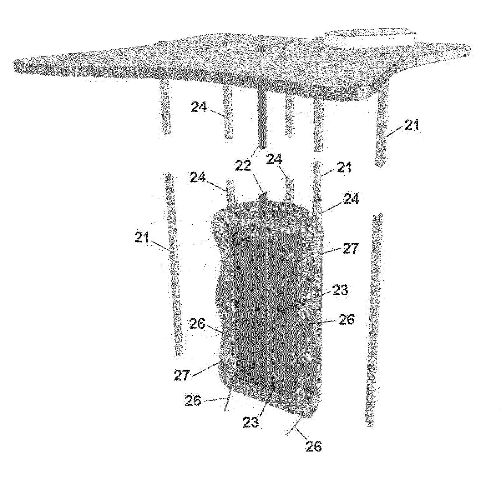
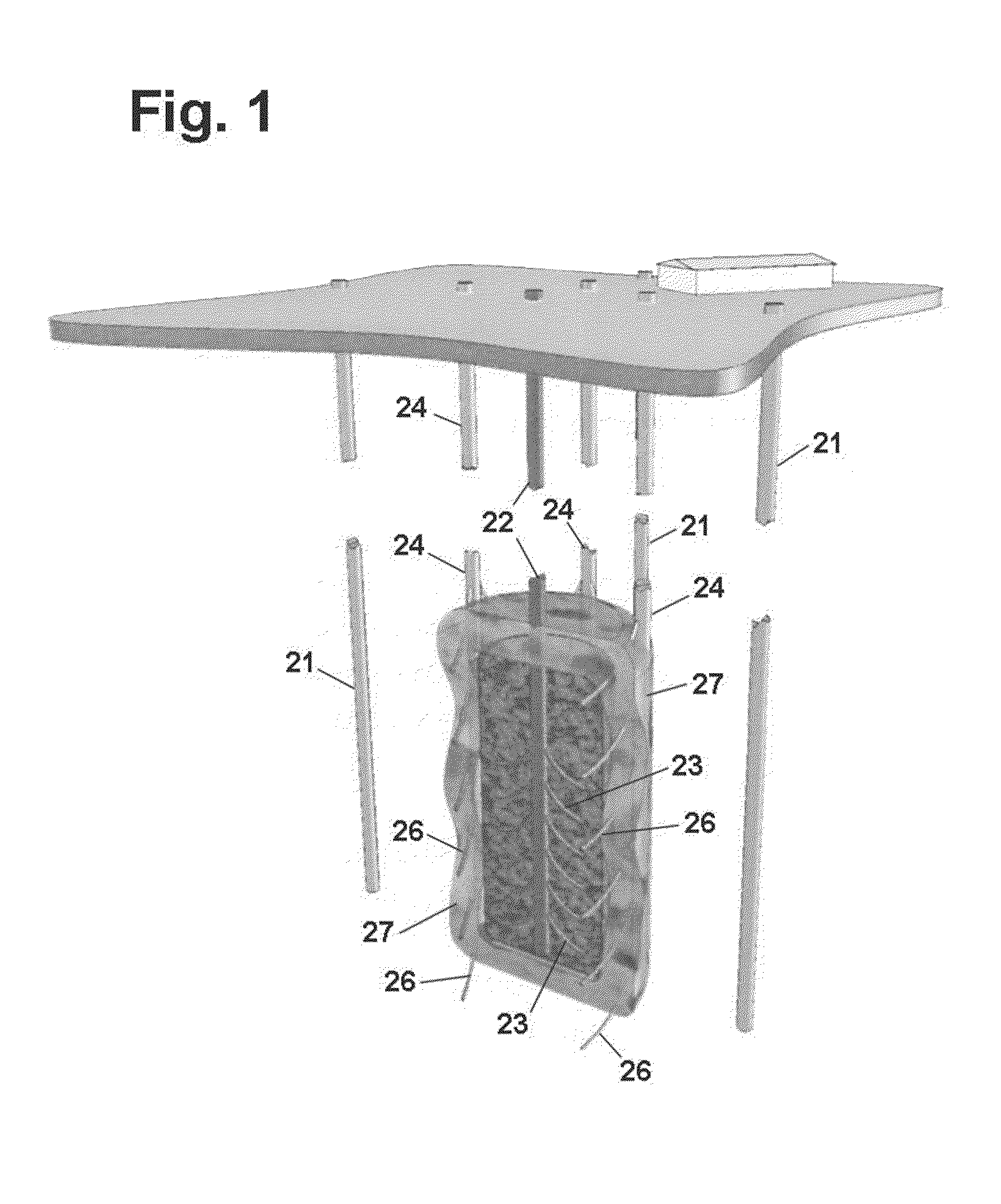
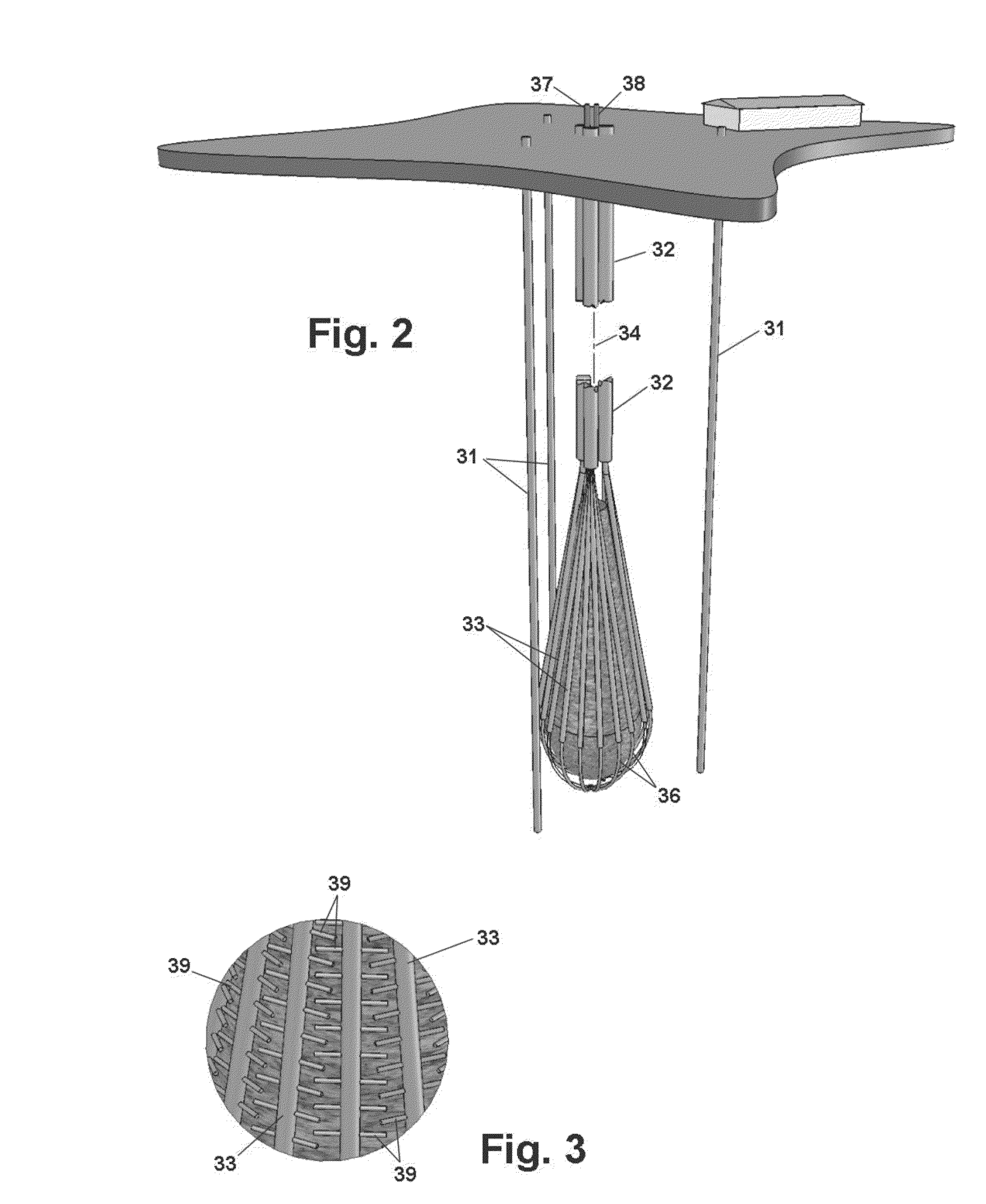
[0023]The invention makes it possible to construct gas or liquids storage reservoirs in many geological settings without conventional requirements for pre-existing void spaces or aquifers or for excavation to create the reservoir space. The reservoir is constructed in rock utilizing natural and enhanced pore space for the storage of gases or liquids. Existing geological fractures and reservoir performance and safety are managed by the injection of barrier material at the perimeter of the reservoir. Surface systems are utilized to manage injection and recovery of the stored gases and liquids, to monitor conditions in and around the reservoir, and to verify or audit the amount of gas or liquid in the reservoir. The result is a coherent reservoir system with a cost consistent with industry requirements, that can be engineered to scale and performance specifications, and be optimally located where such a reservoir is required.

[0024]Before construction of an underground reservoir begins,...


PUM


Abstract

An engineered, scalable underground containment system and method for storing compressed gases or liquids in permeable rock formations using conventional drilling techniques. The porosity and permeability of the formation may be enhanced to maximize reservoir capacity and increase the rate at which gases and liquids can be introduced into and removed from the reservoir. In some embodiments, layers of cap rock in the formation are utilized as containment barriers, and in some, containment barriers are constructed around the storage zones.

Description

RELATED APPLICATION[0001]Application No. 61 / 106,918, filed Oct. 20, 2008, the priority of which is claimed.BACKGROUND OF THE INVENTION[0002]1. Field of Invention[0003]This invention relates generally to underground storage of gases and liquids and, more particularly, to an engineered, scalable system and method for containment of gases and liquids both in virgin rock formations and in formations that have previously been drilled and / or used for storage.[0004]2. Related Art[0005]This invention relates generally to underground storage of gases and liquids and, more particularly, to an engineered, scalable system and method for containment of gases and liquids both in suitable rock formations and in formations that have previously been drilled and / or used for storage.[0006]Heretofore, the underground reservoirs typically used for such storage have included old salt or limestone mines, solution mined salt domes, depleted gas or oil fields, saline aquifers, and other underground sites ha...

Claims


Application Information

Patent Timeline
Patent Type & Authority Applications(United States)
IPC IPC(8): E21B43/26B65G5/00
CPCB65G5/005E21B33/138Y02C10/14E21B43/305E21B41/0064Y02C20/40
Inventor DICKINSON, III, BEN WADE OAKESDICKINSON, ROBERT WAYNEOUSTERHOUT, OLIVER DOUGLASMUSETTI, LAWRENCE JOSEPHUNDERWOOD, PORTER JAMESDANESHY, ALI
Owner SEQENERGY
Why Eureka
Try Eureka